The principle of operation of most measuring instruments is based on the conversion of electrical and magnetic energies. However, under the influence of intense external fields, failures in the operation of electronics are observed [1, 2]. Such fields create interference due to which semiconductor elements and microcircuits can fail. Intense radiation also allows you to gain unauthorized access to various information: with it you can use special remote devices that read data from any electronic gadgets, for example, from a computer or phone. To prevent unwanted failures in the operation of electronics and measuring equipment, as well as to protect confidential information, it is necessary to create a barrier to the external field [3, 4] (electromagnetic, magnetic, electric or all fields at the same time). A screen with high magnetic permeability or high electrical conductivity, equipped around the protected space, creates such barrier [3]. Now, in the digital age, more than ever, it is necessary to ensure uninterrupted operation of electronics and measuring devices, as well as to ensure the safety of information. The importance and relevance of solving the problem of electromagnetic compatibility in the process of designing electronic equipment is confirmed by numerous studies of domestic and foreign scientists and specialists [3, 4, 5].
Based on the foregoing, knowledge of materials for magnetic screens and the principles of shielding is necessary for students studying in the fields of 11.03.03 – Design and Technology of Electronic Tools, 12.03.01 – Instrumentation Engineering Technology and 11.03.04 – Electronics and Nanoelectronics and a number of other areas [6, 7, 8].
Purpose of the study
Identify areas of effective use of screens of various materials and combinations of materials.
Shielding Principles
By magnetic shielding of some area of space is meant the weakening of the magnetic field inside this area by restricting it to a shell made of soft magnetic materials. In practice, another shielding method is also used, when a source of a magnetic field is placed in the shell, thereby limiting the distribution of this field into the environment [1].
The effectiveness of shielding is the ratio of voltages, currents, strengths of electric and magnetic fields in the shielded space in the absence and presence of a screen: Э = U / U‘.
According to the principle of action, electrostatic, magnetostatic and electromagnetic screens are distinguished.
During electrostatic shielding, the electric field is closed on the metal casing of the screen, and electric charges are transferred to the device casing. In this case, the electric field inside the device is equal to zero due to the specific location of the induced charges on the outer surface of the screen. Thus, even a small metal screen can effectively shield the electric field.
Magnetostatic shielding is based on the closure of the magnetic field in the thickness of the screen having increased magnetic permeability. The screen material must have a magnetic permeability significantly greater than the magnetic permeability of the environment.
The effectiveness of such a screen is greater, the greater its magnetic permeability and thickness. A magnetostatic screen is used only with a constant field or in the low-frequency range of a change of this field. For magnetostatic shielding, steel and permalloy of various thicknesses are well suited.
Electromagnetic shielding is based on the interaction of an alternating magnetic field with a field created by eddy currents induced first in the thickness and on the surface of the conductive material of the screen. High-frequency field screening is based on the reflection and absorption of an electromagnetic wave during the transition from one medium to another. An electromagnetic wave interacting with the screen is partially reflected by its surface, partially absorbed by the screen material. These processes lead to energy loss of the wave and its attenuation. For shielding high-frequency fields, the main requirement is the high conductivity of the screen material and the absence of holes, slots, poor contact of the screen elements, that would allow radiation to pass through. Under these conditions, electromagnetic shielding will be effective in high frequency fields.
Equipment, devices and tools
The structural scheme of the complex for studying the effectiveness of using various materials as magnetic screens is shown in Fig. 1. One of the main elements of the complex is the installation [8] which includes a coil 1 on a non-magnetic frame 2 (solenoid) and a non-magnetic base 3. To evaluate the electromagnetic field, a measuring coil 4 is placed in the central part of the solenoid. Terminal sockets 5 of the excitation coil 1 and terminal sockets 6 of the measuring coil 4 are based on 3. To create an electromagnetic field, a special form of signal generator is used 8. The signal from the measuring coil 4 is evaluated by an oscilloscope 10 and a millivoltmeter 11. Samples screens (Fig. 2) are made of different materials in the form of glass of different thicknesses. The material and wall thickness of the corresponding screen sample are given in table. The general view of the complex is shown in Fig. 3.
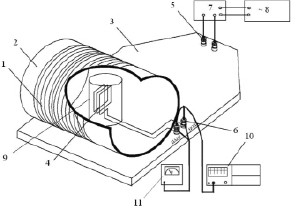
Fig. 1. A complex for the study of materials for magnetic screens
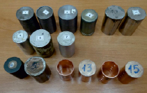
Fig. 2. Screen Samples
Research Methodology
An electromagnetic field is created by using an excitation coil 1 (Fig. 1). The measuring coil 4 is connected to an oscilloscope 10 and / or a millivoltmeter 11. First, the voltage U is measured on the measuring coil without shields. Then, samples of screens 9 of different materials are alternately put on the coil, and the voltage U' on the measuring coil is measured by using an oscilloscope (millivoltmeter). The lower the voltage U' on the measuring coil after installing a sample on it, the more efficient the material acts as a screen.
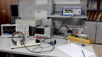
Fig. 3. General view of the complex for studying the effectiveness of shielding an electromagnetic field
The results of experimental studies
|
Sample No. |
Screen material |
Measuring coil voltage without shields U = 100 mV |
||||
|
Wall thickness, mm |
100 Hz |
1000 Hz |
10 kHz |
100 kHz |
||
|
U' |
U' |
U' |
U' |
|||
|
1 |
Steel |
1,4 |
20,2 |
19,1 |
30,1 |
30,4 |
|
2 |
Steel |
2,4 |
12,2 |
18,4 |
28,2 |
27,3 |
|
3 |
Steel |
5.1 |
6,65 |
11,1 |
19,2 |
22,6 |
|
4 |
Permalloy |
0,7 |
53,0 |
56,3 |
26,5 |
25,9 |
|
5 |
Aluminum |
0.5 |
97,5 |
74,9 |
20,8 |
20,0 |
|
6 |
Aluminum |
0.5 |
98,6 |
79,1 |
31,7 |
23,7 |
|
7 |
Aluminum |
1.7 |
95,7 |
45,3 |
17,4 |
22,4 |
|
8 |
Brass |
0,7 |
99,3 |
89,1 |
31,6 |
32,5 |
|
9 |
Copper (foil) |
0,2 |
99,7 |
93,6 |
35,4 |
21,7 |
|
10 |
Permalloy single layer unannealed |
0,2 |
81,2 |
84,2 |
84,2 |
36,9 |
|
11 |
Permalloy single layer unannealed |
0,4 |
75,1 |
76,4 |
69,6 |
20,5 |
|
12 |
Copper 99,99 % |
1,5 |
96,3 |
44,2 |
23,9 |
31,7 |
|
13 |
Copper 99,99 % with cover |
1,5 |
96,8 |
43,1 |
24,5 |
29,8 |
|
14 |
Copper 99,99 % perforation |
1,5 |
97,4 |
45,7 |
24,0 |
30,0 |
|
15 |
Copper 99,99 % perforation with cover |
1,5 |
97,5 |
44,9 |
23,9 |
23,5 |
|
Combination K1 (4 + 9) |
53,1 |
46,9 |
19,4 |
24,4 |
||
|
Combination K2 (6 + 4 + 8) |
52,6 |
29,1 |
15,5 |
25,4 |
||
|
Combination K3 (8 + 1) |
21,3 |
15,5 |
15,8 |
22,1 |
||
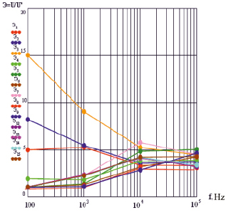
Fig. 4. Graphs of the frequency of shielding efficiency Э of screen samples on frequency
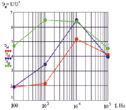
Fig. 5. Graphs of the frequency of shielding efficiency Э of samples from combinations of materials on frequency
To identify the effectiveness of screens from a combination of different materials, measurements were carried out for a combination of several samples: permalloy-copper (a combination of K1 samples 4 and 9); brass-permalloy-aluminum (K2 combination of samples 8, 4 and 6); brass steel (combination of K3 samples 8 and 1).
The measurements were carried out at frequencies: 100 Hz, 103 Hz, 104 Hz, 105 Hz. The results are listed in Table. For the convenience of analyzing the results of the study, graphs are constructed (Fig. 4) as a function of the frequency of screening efficiency of various materials.
The results of the study
As a result of the analysis of the results of the study, it was found:
1. Samples of steel (1, 2) and permalloy are significantly superior to samples of aluminum (5, 6, 7), brass 8 and copper 9, 12, 13, 14, 15 in shielding efficiency in the frequency range from units to 1000 Hz. They are more efficiently used as magnetostatic screens. But even at frequencies from 1 kHz to 100 kHz, they are slightly inferior in efficiency to samples of aluminum and copper. Iron-based steels and alloys, which have high magnetic permeability, also have electrical conductivity. Therefore, they are more versatile.
2. The greater the wall thickness of the steel screen, the better its efficiency (Э3 > Э2 > Э1).
3. The presence of perforations (holes) in the walls of the screens 14 and 15 slightly reduces the effectiveness of shielding, but at the same time provides the best thermal regime of the screened device (component) due to air convection.
4. Samples from unannealed premalloy lose their effectiveness in screening constant magnetic fields. Permalloy is very sensitive to mechanical stress (shock, cutting). Therefore, to restore the magnetic properties, heat treatment (annealing) is necessary. During operation, the screens should be protected from shock using, for example, rubber gaskets between the screen and the housing, to preserve its magnetic properties.
5. In the considered frequency range the highest efficiency has a combination of a sample of steel 1 and brass 8.
Conclusions
In the course of this work, the physical principles of protecting devices from the influence of external magnetic fields were studied. The characteristics of materials and alloys for magnetic screens were studied either. The areas of effective use of various materials and the effect of wall thickness on shielding efficiency were determined experimentally. The application of a thin layer of material with high electrical conductivity (a multilayer screen) onto a screen made of soft magnetic material allows expanding the functionality of the screen and increasing the screening efficiency.

