
Scientific journal
European Journal of Natural History
ISSN 2073-4972
ИФ РИНЦ = 0.204
STUDY OF POWER SUPPLY SCHEMES OF AN INDUSTRIAL ENTERPRISE WHEN CONNECTING OWN GENERATING SOURCE

As the conducted research and accumulated design experience have shown, the presence of a working (non-backup), rather small source of electricity, has a significant impact on the formation of the entire power supply scheme of the enterprise and its operating modes.
There are proposals for various options for connecting mini -thermal power plant devices to power supply schemes, but there is no methodology for choosing one or another scheme.
It is proposed to analyze the power supply system of an existing enterprise when integrating a mini-thermal power plant into it. Based on this, develop recommendations for connecting a distributed generation resource.
The results of this study will reduce energy losses in the distribution network of the enterprise, increase the reliability of power supply to consumers.
In total, there are three options for organizing work with an external electrical network.
A) “island” (independently, without connection to an external electrical network). Advantages: m-there is no need to go through the procedure of approving the operation of the facility with a network organization
Disadvantages:
– requires a reserve of energy to start the “last consumer”;
– strict control over the launch of consumers (combinations of consumers) is required;
– additional restrictions to maintain the quality of electricity;
– there is no way to sell the “surplus”;
B1) work in parallel with the network in the “peninsula” or “one-way parallel” mode (without supplying power to the network), with the organization of an advanced shutdown of its own generation in order to avoid an external short circuit of the power source;
Advantages:
– allows you not to incur additional costs for creating a power reserve;
– allows you not to think about turning on and off large consumers (all irregularities are smoothed out by the external network);
– minimizes the amount of reconstruction of the electrical network (minimum technical conditions of the network organization);
– less network activity and costs than in variants B2 and B.
Disadvantages:
– it is necessary to maintain charging from an external network, which excludes the return of energy to the network while reducing its own consumption (disconnecting a powerful electric consumer);
– it is necessary to go through the procedure of coordinating the operation of the device with the organization of the network.
B2) Work in parallel with the network in the “peninsula” or “one-way parallel” mode (without power supply to the network), without preemptive shutdown of its own generation in case of an external short circuit. In case of an external disturbance in the network, the generation shutdown will be performed only if the pre-calculated parameters of the mode are exceeded, however, it is worth noting that the allocation of own generation to its balanced load of the enterprise is not possible, taking into account its sharply variable nature.
For this option, it is necessary to conduct a more in-depth analysis of the functioning of the external electrical network, namely:
- calculation of short-circuit currents of the adjacent external network to at least 110 kV and above (the input generation will increase the level of short-circuit currents, it will be necessary to check the breaking capacity of switching devices and the thermal resistance of the elements of the external network);
- calculation of the static and dynamic stability of the network, taking into account real models of automatic control of excitation of generators (their own and nearby in the external network).
The pros and cons for option B2 are considered relative to option B1.
“+” In case of some external damage (remote short circuit, shutdown with successful automatic re-activation), its own generation will not be taken out of operation.
“-” An additional set of measures is needed for the design, calculations and coordination with the network organization.
“-” Additional costs are required for the equipment of the external network with relay protection devices (relay protection of the power transmission line “generatornoe switchgear – external network” – for selective disconnection of this power line) and emergency automation;
“-” If the permissible levels of short-circuit currents in the external network are exceeded, it may be necessary to replace network elements (wires, power and measuring transformers, switching equipment, etc.).
It is worth noting that this option is usually chosen by larger producers and consumers of electricity with a more even schedule and, accordingly, the possibility of allocating to their own balanced load (switching to the “island” mode).
Thus, of the considered options A, B1 and B2, option B1 is recommended for implementation, as it is more technically preferable and less costly, and non-selective shutdowns are not expected to cause significant economic damage due to their short duration, non-automatic commissioning of disconnected generators into operation, taking into account additional control of network mode parameters, by the network operator will take several minutes.
B) Work in parallel with the output of power to the network.
This option is characterized by the fact that the generators are constantly loaded at 100%, and the difference between the generated and consumed energy is supplied to the network.
The set of technical measures for this option is similar to B2.
The pros and cons for option B are considered relative to option B2.
“+” the installed capacity is used at 100 %;
“+” there is no need to stop the installation when reducing its own consumption below 50%;
“+” allows you to sell excess electricity to the grid;
“-” organizational measures for the organization of power distribution to the network coordination of design solutions for power distribution, organization of sales.
Taking into account the random nature of its own consumption, this option seems to be unpromising, since in case of its implementation it will be necessary to adjust its own consumption schedule to the need to fulfill the schedule of the electric consumer, which is impractical based on the primary production tasks of the enterprise.
Electrical equipment in a 6-10 kV power supply system is usually designed for a short-circuit shock current equal to 20, less often 31.5 kA.
To limit the short-circuit currents to the required value at the power source – the main step-down substation – transformers with separated low-voltage windings or separated reactors are used (the principle of deep separation).
In combination with the separate mode of operation of the main step-down substation transformers, this turns out to be quite enough. The checkpoint itself is located closer to the center of the load in order to reduce the length and losses in the distribution network (the principle of deep input).
As a switchgear, mainly 6 (10) kV main step-down substation is used Additional switchgears operating at a voltage of 6 (10) kV are intended only for remote consumers or if there are consumers using electric motors, electric furnaces and other devices that require operating switches. Such a power supply system is simple, economical and reliable for consumers of the 2nd, 3rd and in some cases 1st categories, if they have the appropriate external power sources.
If there is a mini-thermal power plant in the power supply system, the following tasks are performed [1]:
* limitation of short-circuit currents that may occur;
* determining the operating mode of generators (parallel to the power system or autonomous);
* the choice between parallel or separate modes of operation of power transformers at the main substation;
* selection of the operating mode of generators of mini-thermal power plants: parallel or separate;
* ensuring dynamic stability in the event of a short circuit in the 6 (10) kV distribution network;
* ensuring high-quality power supply during autonomous operation and sensitivity and selectivity of operation of relay protection and automation;
* ensuring the reliability of the power supply of the directional operating current system at low values of short-circuit currents during the autonomous operation of the generator.
The operation of generators in parallel with the power system can lead to overload of electrical equipment due to a short circuit, which negatively affects the dynamic stability of generators and may interfere with the selectivity of relay protection.
At the same time, when generators work separately on their own load, problems arise with the quality of electricity, the sensitivity of relay protections and the reliability of the supply of operating current in the absence of batteries.
Thermal power plants operate in synchronous mode with other stations and the power system. The use of linear and group reactors on transmission lines with a voltage of 6(10) kV allows them to maintain dynamic stability in the event of a short circuit in the distribution network [2,3].
The use of linear and group reactors also makes it possible to install a selective and high-speed protection system.
In addition, the supply of current for working circuits is provided through the use of traditional batteries.
For small electric generators and mini-thermal power plants, more efficient schemes may be the use of inverters, solar panels, wind turbines and other alternative energy sources. These solutions can provide higher efficiency, cost-effectiveness and dynamic stability of the power supply system. In addition, the use of such solutions can reduce dependence on traditional energy sources and reduce the negative impact on the environment.
Thus, it is necessary to look for other solutions when building a power supply scheme.
Determining when choosing a scheme are:
1. Power, type and number of mini-thermal power plant plants;
2. Power supply scheme from the power system and its performance;
3. Stability of the electrical equipment of the power supply system to the short-circuit currents.
There are several options for connecting generator sets of distribution production equipment of distribution generation with distribution electrical networks or internal power supply networks of industrial enterprises. The choice of a particular circuit depends on various factors, such as the power of a generator set or power plant, its distance from networks of the appropriate voltage class and other relevant factors [4,5].
If the distribution generator facilities are connected to the buses of distribution substations with a voltage of 110-220 kV via transformers, or to the buses with a voltage of 0,4-6-10 kV, then the principles of operation of relay protection and automation in the neighboring network are not subject to change. The volume of electricity flows remains unchanged, since the electricity supply to consumers is carried out through feeders coming out of the neighboring network. At the same time, energy is transferred from the tires to the pipelines.
When the generators of power plants are connected to the supply networks with voltage 0,4-6-10 kV. Therefore, there is a need to rebuild the relay protection and automation system, as well as use more complex protective mechanisms in the neighboring network. This is due to the fact that reverse energy flows occur, which depend on the methods of production and consumption in the load nodes. In such cases, it may be necessary to change the network topology by installing additional switching devices, as well as complete or partial replacement of switching devices due to an increase in the level of short-circuit currents. Topic: power supply and network topology.
Connecting generator sets or power plants of distribution generating equipment to substation buses is the most cost-effective solution. However, it is necessary to take into account the possibility of loss of reliable power supply to consumers in case of accidents on substation tires when all generator sets and consumers are disconnected. The same applies to cases of damage to the power supply device in the head part, when there is no automatic input of a reserve from the consumer. The connection of distribution generation devices to feeders inside the distribution network allows distribution stations to distribute a balanced load in the energy district and provide electricity to consumers until the external power supply network is restored in the event of accidents on the substation tires or the head sections of the feeders. This decision should be made at the stage of development of output power systems, since it has a significant impact on the technical and economic efficiency of the project for the construction of the distribution generation equipment.
Consider the assessment of such an important influencing factor as a change in reliability when the network structure changes due to the connection of its own generating source to the existing power supply system of the enterprise, which has buses, for example, with a voltage of 0.4; 6; 10 kV.
With the simplest schemes with sequential and parallel inclusion of elements, it is possible to calculate reliability (failure rate and probable duration of downtime) based on the parametric method using expressions:
* with serial connection
 (1)
(1)
where λпосл – serial circuit failure rate, 1/year; λk – also k-th element, 1/year; n – the number of elements connected in series;
 (2)
(2)
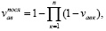
where  – probable duration of serial circuit downtime, i.e.; vавк – the same finding of the k-th element included in the serial circuit, in emergency idle, i.e.;
* when connected in parallel
λпар = λ1vав2 + λ2vав1, (3)
where λпар – failure rate of parallel circuits, 1/year; λ1 λ2 – for each parallel branch consisting of consecutive elements, 1/year; vав1 vав2 – the probable duration of emergency downtime of each parallel branch consisting of consecutive elements, i.e.;
vпар = v(1)ав2 + v(2)ав1, (4)
where vпар – probable duration of emergency downtime, i.e; v(1)ав2 – the same is true of the first branch during periods of emergency downtime of the second branch of the chain, i.e.; v(2)ав1 – also of the second branch during the emergency downtime of the first branch of the chain, i.e.
To calculate the reliability indicators of the power supply of the load node, the replacement scheme of the network in the area between the power sources and the node in question is analyzed. In the scheme, elements are connected sequentially, the failure of any of which causes the downtime of the entire branch, and branches are connected in parallel, the shutdown of any of which does not lead to the downtime of others. In addition to the elements of this branch, adjacent switches are also introduced into the serial circuit, the failure of which, with the development of an accident, will lead to the disconnection of the circuit under consideration (for example, switches of all connections of the bus section to which the analyzed circuit is connected).
Thus, to ensure the reliability of power supply schemes, it is necessary to take into account the initial states of individual elements, i.e., reliability indicators are calculated for relatively short periods of time. To estimate the probabilities of the state of systems over a sufficiently long period of time (annual period, year), in the vast majority of cases, simpler asymptotic methods based on the average values of the probabilities of the state of the elements can be used.
To solve these difficulties, software has been developed that automates the entire process of analyzing the reliability of power supply systems. All possible methods of electricity transmission to each consumer have been identified and their reliability indicators have been calculated. The work of the program is shown by the example of a part of the Kstov networks.
The possibility of using the hierarchical analysis method to determine the optimal network configuration is determined. Reliability indicators were taken as criteria, but the list of criteria may be expanded in the future.
Библиографическая ссылка
Белов Я.Н., Павлычева Т.Н., Кулигина Н.О. STUDY OF POWER SUPPLY SCHEMES OF AN INDUSTRIAL ENTERPRISE WHEN CONNECTING OWN GENERATING SOURCE // European Journal of Natural History. 2023. № 3. ;URL: https://world-science.ru/en/article/view?id=34344 (дата обращения: 26.07.2026).
DOI: https://doi.org/10.17513/ejnh.34344