
Scientific journal
European Journal of Natural History
ISSN 2073-4972
ИФ РИНЦ = 0.204
INVESTIGATION OF CHARACTERISTICS OF FRACTAL WIRE ANTENNAS MADE IN THE FORM OF KOCH CURVE

Wire antennas are extremely widely used due to its advantages [1]:
– ease of manufacture and availability of materials;
– design repeatability;
– possibilities to achieve high efficiency;
– availability of software for calculation of this type of antennas.
The main requirements for designing wire antennas are [2]:
– formation of a beam pattern in accordance with the purpose of the antenna (narrow main lobe of the pattern with minimization of the value of the remaining lobes to achieve acute beam, or implementation of a uniform circular beam);
– provision of antenna resonance at a certain frequency (or several frequencies) or broadband property;
– consistency with transmission line im- pedance;
– reduction of maximum overall dimen- sions.
Recently, the study of the capabilities and properties of fractal antennas [3, 4], the form of which has the property of self-similarity (there are a lot of such forms), has gained great popularity. However, the methods considered in the literature are either too time-consuming, or are devoted to the study of any separate characteristic. The general theory of wire antennas of any configuration does not yet exist.
Therefore, at the current stage of development of this direction, it is necessary to create a fairly simple and universal methodology for the least time-consuming study of the characteristics of fractal wire antennas, on the basis of which they can be optimized.
Purpose of the study
In connection with the above considerations, the purpose of the work was to develop a universal method for creating and calculating models of fractal antennas and consider it using the example of an antenna in the form of a dipole geometrically representing a Koch curve.
The study includes the creation of a Python program to find the coordinates of the beginning and end of the sections of the curve forming the antenna profile, bringing these coordinates into a special program for calculating the characteristics of antennas and finding the following indicators: antenna resonance frequencies according to the values of the reflection coefficient, as well as the construction of a beam pattern in two planes – horizontal H and vertical E. The method being developed should be simple and convenient to use.
Also, for comparison, it is necessary to calculate the characteristics of a simple antenna of a classical form – a half-wave dipole having the same resonant frequency as antenna in the form of a Koch curve.
Based on the results of the study, it is necessary to draw conclusions on the feasibility and areas of use of antennas having the fractal form under consideration and develop recommendations for further research of fractal antennas.
In this work, one of the embodiments of the Koch curve (Fig. 1), located in the coordinate system X, Y, Z, is considered.
The length of the entire antenna along the X axis is taken to be 1 m, based on which the fractal Koch curve is built. At the point of intersection of the curve with the Y axis, a sinusoidal electric signal of a certain frequency f, Hz (with the corresponding wavelength λ, m) is supplied.
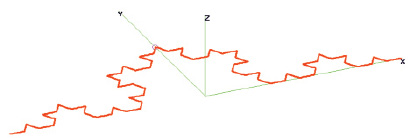
Fig. 1. Design diagram of the studied fractal antenna
Materials and research methods
To create models of wire antennas in the form of fractal curves, you need a tool to calculate the coordinates of their characteristic points. In Fig. 1, the characteristic points are the beginning and end of the curve, as well as the vertices of the numerous angles from which it consists. As such a tool, it was decided to use the Python program, which is distinguished by the availability of all the tools necessary for this, the simplicity of writing program code and the free use of all function libraries.
To date, the author has accumulated quite a lot of experience in creating programs using this universal language, including already there is a developed program for constructing Koch curves [5]. To solve this problem, this program has been modified as follows: using the Pandas library, it is organized to output the coordinates of all characteristic points to the Excel table.
The coordinates of points obtained with the help of the program are used to form the original data file for the 4NEC2 program, which is also free and easy to use, but has the functionality and accuracy necessary for solving the tasks.
Calculation of characteristics in this program is performed using moment method [6]. The antenna is represented by separate interconnected straight wire sections (for example, for the antenna shown in Fig. 1, there are 65). At the point located on the Y coordinate axis, a small area (indicated by a circle) is pointed to supply electric current (the current parameters are selected automatically by the program). The wave resistance of the supply conductor is assumed to be 50 ohms (impedance of the coaxial cable).
According to the method of moments, each antenna wire is divided into several segments in which concentrated loads are located [7]. In this case, to ensure high calculation accuracy, the number of segments of each conductor is taken to be 9. The lead conductor is located on the middle segment of the 33rd wire.
In the underlying program 4NEC2 method, the integral equation characterizing the antenna field is laid out according to a system of basic orthogonal functions, followed by reducing the problem to a system of linear algebraic equations.
The Python-based coordinate file for Excel is simply converted to the structure required by the 4NEC2 program (with few additional antenna system input parameters added to the point coordinates) and then saved in a text file with the .nec extension. After loading the received file into the program, the geometric model of the antenna shown in Fig. 1 is 4NEC2 obtained.
The 4NEC2 program makes all subsequent calculations, which include:
1. constructing a dependence of the reflection coefficient on the frequency of the supplied signal and finding resonant frequencies of the fractal wire antenna;
2. drawing a directional pattern of a fractal antenna in a horizontal plane in a polar coordinate system;
3. embodiment of claims 1 and 2 for a simple wire antenna, a half wave dipole.
Research results and discussion
An antenna with a length of 1000 mm along the X coordinate axis, with a conductor thickness of 1 mm, is examined. Is it necessary to consider an antenna – a half-wave dipole of the same length along the X axis (half-length of the λ/2 = 0.5 m), for which the resonant frequency is
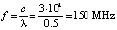
(c is the speed of light, m/s), then for a fractal antenna the resonance should be lower than this value, since the total length of the conductor of the antenna in question significantly exceeds 1000 mm.
Therefore, the calculation of the reflection coefficient was carried out in the 4NEC2 program at frequencies of 150 MHz and below (up to a frequency of 10 MHz) with a step of changing the frequency of 1 MHz. Conventionally, we call this calculation preliminary, since the frequency step is quite large (this had to be done forcibly, since the number of points on the graph should not exceed 256, according to the requirements of the program). The resulting graph is shown in Fig. 2.
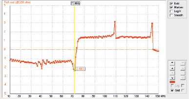
Fig. 2. Results of preliminary calculation of antenna reflection coefficient
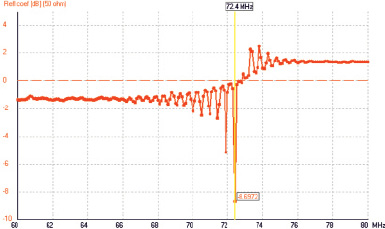
Fig. 3. Results of refined calculation of antenna reflection coefficient
The graph shows that the reflection coefficient K has the smallest value at a frequency of about 71 MHz, there is also a decrease in K at a frequency approximately 2 times lower. From the presented results, it can be concluded that the resonant frequencies of the antenna are close to these values, however, in order to find them more accurately, it is necessary to make calculations near the presented frequencies, but with a smaller frequency change step (with an updated calculation, it is adopted equal to 0.1 MHz).
The graph obtained when calculating the reflection coefficient K near the frequency of 71 MHz is given in Fig. 3.
According to Fig. 3, the refined main resonant frequency of this antenna is 72.4 MHz. Similar calculations were carried out near twice the frequency – it turned out that there is a second resonance of the antenna system, but the reflection coefficient there is higher (about -6 dB).
Further, for the main resonance of the 72.4 MHz system, the antenna directivity patterns in the horizontal and vertical planes were built using the 4NEC2 program.
It turned out that in the vertical plane the antenna is non-directional, like a half-wave dipole. The directional pattern in the horizontal H plane (X-Y as shown in Fig. 1) is shown in Fig. 4.
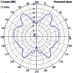
Fig. 4. The directional pattern of the fractal antenna in the H plane
It can be seen from the figure that the antenna has no acute directivity in any direction – the diagram is complex, but does not allow using the studied fractal antenna as a directional one.
The next stage was the task of creating a model and studying an antenna – a half-wave dipole having the same resonant frequency as a fractal antenna in the form of a Koch curve (72.4 MHz). Since the length of each arm of the half-wave dipole is one quarter of the wavelength λ /4, it is
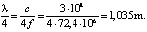
The length of the entire dipole is thus 2.07 m (that is, more than 2 times the length of the fractal antenna).
In the 4NEC2 program, a model of this half-wave dipole was built, the arms of which are located on the X axis, and the current supply is at the origin.
The method of calculating the half-wave dipole using the 4NEC2 program is no different from the method of calculating the fractal antenna. As a result of the calculation, the antenna resonance frequency was verified to a minimum of reflection coefficient, and directional patterns were built in the planes H and E. The theory was confirmed that in the vertical plane E the half-wave dipole does not have directivity (radiation in all directions is the same). In the horizontal plane, the directivity pattern characteristic of the half-wave dipole is also obtained (Fig. 5).
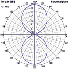
Fig. 5. The directional pattern of the half-wave dipole in the H plane
The figure shows that the dipole in question has a certain orientation along the Y axis, more pronounced than that of the fractal antenna in the form of a Koch curve.
Сonclusion
The obtained results make it possible to draw conclusions and develop recommendations on the design and use of fractal wire antennas made in the form of a Koch curve:
1. the main advantage of a fractal antenna is its much shorter length compared to a half-wave dipole having the same main resonance frequency, so a fractal antenna can be recommended for use in small devices (and at small wavelengths – and in mobile devices);
2. the fractal antenna in this case has two resonant frequencies multiple of each other, but the smaller resonant frequency has a higher reflection coefficient, and at this frequency the antenna operates less efficiently;
3. compared to the usual half-wave dipole, the fractal antenna has less directivity in the horizontal plane, so it is recommended to use it for such devices as radio and television receivers, digital signal receivers, electromagnetic radiation meters.
The dimensions of the fractal antenna while maintaining the given resonant frequency can be reduced even more, increasing its fractal dimension (by reducing the size of self-like elements – triangles and increasing their number). To achieve even smaller dimensions, a fractal antenna could be designed to operate at a second, lower, resonant frequency.
In further studies, it is also necessary to check the effect of conductor thickness on the characteristics of the fractal antenna – this seems important in this case, since increasing fractal dimension requires reducing the thickness of the conductor, otherwise it will be impossible to correctly repeat fractal parts of the antenna of small size.
As can be seen from the study, fractal antennas in the form of a Koch curve are suitable for use in the same wavelength ranges as half-wave dipoles, however, as the above studies showed, for each frequency there is only one optimal dimension ratio. To turn a fractal antenna into a wide-loose antenna, it seems that it is necessary to increase the complexity of the fractal structure and simultaneously use a system of antennas of different sizes (as is done, for example, for television antennas, which can consist of a large number of half-wave vibrators).
Summing up the work done, the following tasks can be noted:
– substantiation of the need to create a new, easy-to-use method for calculating fractal wire antennas;
– the algorithm was compiled and the program code was written to calculate the coordinates of the characteristic points of the fractal antenna in the form of a Koch curve, using the Python language modules and functions necessary for this;
– it is shown how the calculated fractal structure can be used in the calculation program of wire antennas 4NEC2 to find resonant frequencies and construct directional patterns;
– comparing the calculated characteristics of the fractal antenna and a half-wave dipole having the same main resonance frequency;
– recommendations on the scope of fractal antennas in the form of the Koch curve, as well as on their further improvement, were developed on the studies carried out.
The approach described in the article is also useful for the optimal design of wire antennas having any fractal configuration [8], but for each type of fractal structure it is necessary to develop its own program code for calculating the coordinates of characteristic points using the Python language, using the corresponding function libraries [9]. In particular, when creating an array of data on the coordinates of a complex antenna module, the Numpy library [10] can be successfully used.
Библиографическая ссылка
Ильичев В.Ю. INVESTIGATION OF CHARACTERISTICS OF FRACTAL WIRE ANTENNAS MADE IN THE FORM OF KOCH CURVE // European Journal of Natural History. 2021. № 2. ;URL: https://world-science.ru/en/article/view?id=34163 (дата обращения: 13.07.2026).