
Scientific journal
European Journal of Natural History
ISSN 2073-4972
ИФ РИНЦ = 0.204
MODERNIZATION OF AUTOMATION SYSTEMS OF THE STAGE OF PYROLYSIS OF ACETIC ACID

The correctness of operation of process automation systems depends to a large extent on the correctness of automation tasks, selection of stabilized parameters, control actions, development of control algorithms, presentation of control information to personnel, as well as on the correctness of the adopted design solutions, content, and design documentation.
The use of automation systems based on microprocessor and computer equipment can significantly increase the efficiency and safety of production. These systems also have a number of advantages -such as high reliability, speed of information processing, compactness, ergonomics, and high functionality. Moreover, their use is mandatory for explosive industries. Therefore, competent selection of automation equipment is the most important task in design.
Purpose of research
The purpose of the study is to modernize the automation systems of the stage of pyrolysis of acetic acid.
Analysis of the technological process as a control object
The technological process for the production of acetic anhydride is based on the catalytic pyrolysis of acetic acid in the presence of a catalyst, triethylorthophosphate, to ketene, water and by-products, followed by cooling, absorption (chemisorption) of ketene from a mixture of pyrolysis gases with regenerated or synthetic acetic acid to form acetic anhydride and distillation of acetic anhydride [1].
The stages of evaporation and pyrolysis of acetic acid and cooling of the pyrolysis gases are carried out continuously on four working streams.
The stages of ketene absorption, washing of gases, rectification of crude acetic anhydride, distillation of acetic anhydride are carried out continuously on two working streams.
Acetic acid pyrolysis process
Acetic acid pyrolysis is carried out in two-section coil pyrolysis furnaces pos. 8 / 1-2. Each pyrolysis furnace has 2 combustion chambers and 6 pyrolysis towers, in which coils from sychromeal pipes are mounted. The coils are connected in 2 parallel lines with 3 coils in each. There are 1 or 2 pyrolysis furnaces in operation.
Vapors of acetic acid, water and triethyl phosphate pass sequentially through 3 coils installed in the towers of the pyrolysis furnaces, in which they are heated from a temperature of 130–170 °С to a temperature of 680–730 °С.
The coils of the pyrolysis furnaces are heated by flue gases resulting from the combustion of natural gas in combustion chambers in a hot air environment. The natural gas: air ratio is automatically or remotely controlled. The excess air ratio should be 1.71–2.00. From the GRU (gas control device) to the burner of each section of the pyrolysis furnace, no more than 120 m3 / h of natural gas is supplied with a pressure of 0.4-1.5 kPa. The completeness of natural gas combustion is monitored by a gas analyzer and visually. With complete combustion, the fraction of oxygen in the flue gas should be 5.6–6.6 %.
Fresh air for burning natural gas is taken from the atmosphere by a fan pos. 9 / 1-2, passes through the air heater pos. 10 / 1-2, where it is heated to a temperature of 200–250 °С and then enters the combustion chamber. Air pressure 0.4–2.4 kPa. The air heater is a two-way shell-and-tube heat exchanger – through a rectangular air section.
Flue gases and air move countercurrently in the air heater. Flue gases are sucked out of the last towers of the pyrolysis furnaces through air heaters pos. 10 / 1-2 exhaust fans pos 11 / 1-2. For uniform heating and dilution of the combustion products to the desired temperature, partial flue gas recirculation is performed. Recycled flue gases cool the construction of the combustion chambers, dilute the hot flue gases and contribute to uniform temperature control in the towers of the pyrolysis furnaces. Due to draft by exhausters in the combustion chambers, a vacuum of 0.015–0.050kPa should be maintained. In the air heater, the flue gases are cooled by air to a temperature of 300-400 °C and through two pipelines are partially supplied to each combustion chamber (for recirculation), the rest through the chimney is released into the atmosphere.
With the complete combustion of natural gas, a temperature of 1200–1280 °C develops under the set of combustion chambers. The heating of the furnace is regulated so that the temperature inside the coils in the pyrolysis zone is maintained within 680–730 °C. In this case, the temperature of the flue gases at the entrance to the first tower of the pyrolysis should be 1000–1100 °С, at the entrance to the second tower – 700–900 °С, at the entrance to the third tower – 500–700 °С, at the exit of the third tower – 400–500 °C. The temperature of the gas-vapor mixture at the outlet of the second coil should be 550–650 °C, at the outlet of the third coil – 450–600 °C.
Vapors of acetic acid, water and triethyl phosphate move in the direction from the third tower to the first. At a temperature of 680–730 °С and a vacuum pressure of –55 ... –70 kPa at the outlet of the third coil in the presence of a catalyst (triethyl phosphate), acetic acid decomposes into ketene and water by the reaction:
СН3СООН → СН2СО + Н2О.
The process is accompanied by adverse reactions [2]:
СН2СО → С +Н2 + СО,
2СН2СО → СН4 + С + 2СО,
2СН2СО → С2Н4 + 2СО,
СН3СООН → СН4 + СО2.
In one pass through the coil, 80-85 % of the supplied acetic acid is converted (decomposed). The pyrolysis products consist of 45-55 % ketene, 10-25 % acetic acid vapor, 25-30 % water vapor and 10-15 % decomposition by-products (data are given in mass percent).
As by-products in the pyrolysis process are formed: methane, ethylene, carbon dioxide, carbon monoxide, hydrogen, carbon (soot). Soot is deposited on the walls of the coils of the pyrolysis furnaces and thereby reduces the throughput of the coils. Therefore, the coils are periodically cleaned – burning soot by blowing them with water vapor and compressed air.
Before starting and stopping pyrolysis furnaces, as well as for emergency cases, it is possible to purge the coils with compressed nitrogen with an overpressure of not more than 0.3 MPa.
At the outlet from the coils of the pyrolysis furnaces, ammonia with an overpressure of not more than 0.15 MPa and a volumetric flow rate of 0.3-0.5 m3 / h is added into the vapor-gas mixture to stabilize the reaction products [3].
The video frame of the process mnemonic diagram is shown in Figure.
Results of a research
Having analyzed the systems of automation of the pyrolysis process at different enterprises it can be concluded that the need to modernize existing systems is related to its non-compliance with the current rules, unreliablity, and necessity to use a large amount of manual labor. The use of microprocessor and computer equipment, modern devices, and automation facilities is a new approach to solving problems of automation of the process of acetic anhydride production at enterprises.
The management system currently in place at the plants provides the following functions:
• Process parameters are monitored, indicated, and recorded;
• Stabilization of process parameters, namely pyrolysis gas temperature at the outlet of the third coil by changing natural gas flow rate and air pressure;
• Warning • Warning sound and light signaling of deviations of preset process parameters from the norm;
• Interlocks ensuring the system safety in cases when the deviation from the norm reaches the value at which emergency situations may occur.
Thermoelectric converters, such as platinum-platinum type TPP and chromel-aluminium type TCA, which work in a set with showing and self-pointing potentiometers single-point and twelve points, located on the board of the instrument department, are used as temperature sensors. Copper resistance thermal transducers of TCM type are also used.
Membrane pressure gauges and vacuum gauges are used as pressure sensors. Signal from vacuum meters is transmitted to secondary devices. Membrane separators are used to prevent aggressive medium ingress into instruments of the type. Measurement of vacuum under the roof of combustion chambers is performed by means of membrane weight gauge.
Sensors of volumetric flow rate of natural gas that use a chamber diaphragm of ДК-6 type and pressure sampling work together with membrane differential pressure gauges DM.As air pressure sensors, pressure sampling devices are used, which work together with membrane differential pressure gauges DM.
Process parameters are indicated and recorded on secondary devices located on control boards. The large number of different instruments and their dispersion on the instrument board creates difficulties for the operator in observing the process and requires a concentration of attention throughout the shift.
The flow rate of air supplied to burners is estimated by the indirect parameter – air pressure.
The use of secondary instruments and mechanical meters for reading and recording economically important parameters, such as natural gas consumption, brings additional difficulties related to low accuracy, frequent verification, calibration of instruments, and manual processing of diagrams.
Manual processing of diagrams entails unavoidable errors in calculations associated with significant recording error on the self-driving instrument and subjective error.
During start-up and shutdown of the process, most control circuits are transferred to manual control, as in these cases analytical work of operators is required, which is not handled by the existing automation system. The quality of the decisions taken in this case depends largely on the qualifications of the operational personnel.
After analyzing the existing management systems at the production facilities, there were marked shortcomings:
• Does not meet the requirements of reliability of control parameters for determining process explosion hazard at facilities with process units of Category I and II. Explosion hazard controls are provided by duplication of parameters control systems, availability of self-diagnostics systems with indication of operating condition, and with comparison of values of technologically related parameters.
• Most enterprises have developed their own automation devices and equipment resources which may result in frequent failures of control systems.
• Lack of flexibility and scalability, i.e. more functional blocks are required to implement new control algorithms.
• Pyrolysis gas temperature control at the outlet of drop separators is not provided. It is also not possible to control the thermal mode of the furnace.
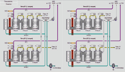
Video frame of process mnemonic diagrams
The analysis shows that the current automation system in production has a number of significant shortcomings, which do not allow control of the process with maximum efficiency, lead to overexpenditure of raw materials and energy resources, and increase the risk of emergency situations.
An important issue is the selection of the appropriate level of automation. The use of local automation means is not feasible in this case, in view of the poor scalability and low reliability of such a system due to the presence of a large number of elements. Therefore, the use of microprocessor equipment and automation at the level of APCS is required. Modern APCS is characterized by perfect organization of information flows, almost complete automation of processes of its reception, processing and provision, possibility of active dialogue of operational personnel with microprocessor equipment in the process of control to develop the most effective solutions.
The most important task is to maintain the regulated temperature of pyrolysis gases at the outlet of the third coil of furnaces. The furnace has high inertia, but the main disturbance effects are insignificant and change slowly: the ASG is supplied from the evaporation stage, where its temperature and flow rate are stabilized; Air is heated in the air heater, its temperature changes slightly and slowly due to inertia of thermal processes in the air heater; The heat transfer coefficient can change by a significant amount only after a long period of time; Heat loss will also change slightly due to quality heat insulation; Flue gas recirculation promotes uniform distribution of its temperature throughout the furnace volume. Thus, it is possible to apply the simplest solution: single-circuit ATS.
The temperature in the furnace combustion chamber is controlled by changing the flow rate of the natural gas supplied to the burner.
In order to control the combustion process, it is assumed to use cascade ACR, in which the setting of the ratio to the regulator is corrected by the flue gas composition regulator, which provides stabilization of oxygen concentration in the flue gases. The presence of oxygen in the flue gases is due to the fact that, in order to ensure complete combustion of the fuel, the combustion process must be carried out with some excess air compared to the theoretically necessary air.
In addition to the technological requirements for the protection parameters of furnaces, restrictions are imposed on explosion safety conditions and requirements for labor and environmental protection [4]. In particular, the coefficient of excess air has to satisfy to restriction of γН ≤ γ ≤ γ. In addition, in order to prevent flue gases from entering the atmosphere in the furnaces, it is necessary to maintain a predetermined vacuum created by the traction by the smoke pumps [5].
Pyrolysis gases are cooled in refrigerators representing 12 sections of “pipe-in-pipe” type, as well as additionally in a drop separator, into the jacket of which brine is supplied after the refrigerator. The controlled parameter is the temperature of the gases at the outlet of the drop separator. The control effects are changes in the flow rates of the recycled water and brine supplied to the refrigerator. At present, there is no possibility of temperature control; cooling carriers are supplied by pumps at constant flow rate, which is extremely inefficient.
The simplest and most efficient solution is to use control using the ASG temperature downstream of the seventh section as an intermediate coordinate. The essence of the solution is that an additional temperature sensor is installed in the refrigerator to measure the temperature of the ASG at the outlet of the seventh section of the refrigerator along the ASG; Setting the ASG temperature at the outlet of this section within 350-400 °C, control of this temperature will be carried out by changing the flow rate of recalculated water supplied to the refrigerator; Temperature control of pyrolysis gases at the outlet of the drop separator (15-20 °C) will be carried out by changing the brine supply.
It is also necessary to provide an indication of process parameters in place, which is not present in the existing automation system. Indication is performed on liquid crystal indicators equipped with sensors.
The existing board system should be replaced by microprocessor controlled computer equipment implementing integrated control, alarm, and interlocking functions.
Signaling is carried out at the operator ‘s station.The blocking function is implemented by means of the software and technical module [6].
CAS and operator station are located in CCP. To monitor and control the process, the operator must provide information about the process parameters. The operator station provides for process visualization on the screen. The operator must also be able to enter setting values from the keyboard and manually lock if necessary. All control functions are performed by the controller. The number of monitoring and control points is planned to remain unchanged: the pyrolysis stage is also controlled from the operator’s station.
Conclusion
The abovementioned shortcomings of existing production systems are the basis for the introduction of a new automation system which will take into account the shortcomings of the existing systems and the latest developments in this field.
Modernization at these production facilities is carried out in order to ensure economy and increase safety, which are the main tasks in any industrial production.
Библиографическая ссылка
Кулигина Н.О., Павлычева Т.Н., Плеханов Е.Е. MODERNIZATION OF AUTOMATION SYSTEMS OF THE STAGE OF PYROLYSIS OF ACETIC ACID // European Journal of Natural History. 2020. № 6. ;URL: https://world-science.ru/en/article/view?id=34138 (дата обращения: 02.08.2026).