
Scientific journal
European Journal of Natural History
ISSN 2073-4972
ИФ РИНЦ = 0.204
FEATURES OF DESIGNING CONVEYOR SCRAPERS AND CHAIN TURN ZONE DURING VIBRATION

For pillar mining of coal and potash salts in the USA there are used room technologies and there is developed a system with a rotary belt conveyor-train. Its industrial results are higher than the ones achieved in the traditional systems. Such a technology was developed in Karaganda in 1980-1987 (chief designer Ponomarev B.Ya.). Alongside with the belt conveyer there was also considered a chain scraper conveyor [1, 2]. Its testing showed great dynamism of the design, breakdown of the scrapers and the chain of the conveyor. The renewal of the designing works [4–6] required the analysis of the breakdown reasons.
Features of the design model
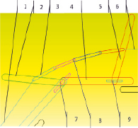
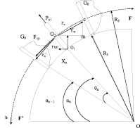
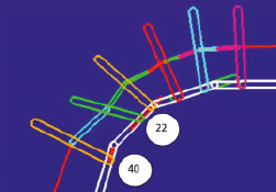
At the movement of the system consisting of several joint parts under the impact of the tractive force the transfer of forces from one part to another takes place successively. The parts experience multidirectional strains from the tractive force, the parts mass and the forces of interaction. There emerge consecutive multidirectional movements with inertia forces in the parts. Even in one separately taken part there emerge different areas which are displaced from each other with acceleration that leads to vibration. In mathematical models it becomes simpler. Some problems for scraper and belt conveyors are similar [3, 5–7]. Let us consider the movement of the conveyor scrapers. To each scraper there is attached a chain piece of 4…7 parts, Figure 1a (all the diagrams and images of scrapers in the movement are personal computer screen photocopies in the course of modeling). The average dimensions of scrapers are 0.3…0.8 m, the chain link to 0.1 m, weighing up to 10 percent of the weight of the scrapers, therefore their impact on the system movement should be considered. The scrapers can be supported at the end faces on the side surfaces of the troughs in which the scrapers move. There is considered the design providing turning the transportation direction due to the gradual turning of the trough at the angle from 6 to 20 degrees. For turning at 90o there are used from 4 to 10 troughs, Fig. 1, a. The study was begun with 2 scrapers connected among themselves by 4 chain links with the maximum angle of the troughs turning from each other. Modeling such a system requires making up a system of differential equations. Their solution is carried out by numerical methods. In Figure 1b there is shown an idealized diagram for designing the parameters of scrapers of the angular conveyor.
Basic systems of equations
Projection to the Y axis of the tractive force from the chain acting on the scraper with the number n in the hinge joint of the chain with the scraper to the right of О2:
Fny = Fn*Sin ((90° + θ)/2 – αn), (1)
the force of resistance of the part of weight G0 on the scraper and the scraper itself (the friction coefficient ftр):
Ftр.y = G0*ftр * Sin (90° – αn), (2)
the scraper tractive force to the left of the scraper О2:
Fn’y = Fn’*Sin ((90°-θ)/2 – αn), (3)
the centrifugal force of inertia from the rotary motion is directed from the center of the turn from the center of the weight О2 of the scraper and the weight:
Рyi = mпр*(ds/dt)2/R2. (4)
The weight displacement is interfered by the resistance force Ftрi. It is directed to the center of rotation:
Ftрi = G0*ftр. (5)
In the solution there is not considered the scraper end friction on the trough at the place of supporting. The tractive force:
F = x1 + x2 + ....xn + F’, (6)
F = y1 + y2 + ....yn + F’, (7)
where F’ is the tractive force of the chain at the beginning of the turn.
The equations are formed from the sums of projections of forces acting on the scrapers in the turn zone on the s X and Y axes. There are added the equations of the moments, for example, relative to the O1 point for each scraper and the chain link. The system of differential equations can be obtained similarly considering the scraper movements on the troughs plane parallel. Linear speeds (derivatives) can be obtained proceeding from the parameters of the rotary motion. The equations are made up on three axes.
Features of solution and results
Solution of such problems is known in packages where the dynamic volume problem is solved due to the linear sampling of differential equations (ADAMS).
The task gradually became complicated. At the beginning there were considered 2 scrapers connected by 4 links of the chain, and later on their number was increased, the types of hinges changed. The plane ones were replaced with the volume ones. The scrapers moved in their own troughs each. The designs are modeled by the Link links, with set dimensions, weight and axial moments of inertia. The troughs are connected with the basis and are not mobile, they are located at the angle to each other, Fig. 1, а. The scrapers and the chain links are connected by rotary spherical hinges. The scrapers from the side of the smaller radius of turn will be pressed to the troughs, therefore their kinematic connections are executed on one side. The scraper connection with the troughs is progressive. Then it will be added with a link connected progressively with the trough and the plane rotary hinge with the scraper. It will permit the scraper to rotate relative to the mounting axis to the chain hinge and to bend relative to the trough. At the beginning the angle is equal to 90 °.
In Fig. 2 there is shown changing the forces of the support reactions in both boards of the troughs and hinge of the chain central link. Studies showed that in case of the gravitation action on the Y and Z axes the angular trough displacement in the turn zone will be the defining factor of vibration of the support reactions of the scrapers with the troughs. It determines the maximum amplitude of vibration of the support reactions, as well as vibration of the slave scraper relative to the hinge of the chain and the turning hinge with a slider, as well as vibration of the chain on the whole, Fig. 2.
a b
Fig. 1. Location of the scrapers and the chain links and their movement (а); an idealized diagram of loading on the rotary troughs (b): 1,6 – tractive forces direction; 2,5 – scrapers in the end of the run; 3 – the chain links; 4 – troughs;7,8 – hinges in the bottom and top troughs, 8 – spherical hinge of the chain central link
In the conditions of the abovementioned scrapers and chain dimensions and weigh, as well as the load of 500 kg applied to the first scraper and 350 kg applied to the last scraper, with directions parallel to the trough boards the vibration of loading are considerable and reach 400 %. The chain (links between the scrapers) within the scraper movement in one trough makes at least 2 full waves and in general the visual picture qualitatively matches that for the chain of the conveyor and the traction chain of the combined machine in case of their observation in the laboratory. Increasing the scrapers weight up to 55 kg for the purpose of imitating the weight transportation leads to increasing instability of the scraper movement, Fig. 1, a. When ensuring the scrapers rotation in the hinge joints to the chain and to the hinge of the pseudo-slide of the trough by the moment of the scraper approaching the end of the trough, the latter bends significantly (to 45 °), Fig. 1, a.
At the same time to model the weight by the scraper mass is not always correct, since in the inertial movement the scraper and the weight are not always connected and do not impact each other, though for a part of the weight that “runs down” the scraper the possibility of the “tripping” is real. However it is also possible in case of oversize materials getting onto the conveyor.
In the provided cases the reactions on the Z axis are not large in comparison with those acting in the turn plane. With increasing the weight their values increase a little, therefore, actually, the scrapers movement is considered in the XY plane. Studies permit to consider the problem that it is structurally possible to provide a hinge joint of the scraper in its middle with the chain. Here the chain link is usually fixed strictly by means of a threaded design. In reality the scraper has no special slide pair for connection with the trough, however the accepted simulation reflects correctly the work of the scraper pressed to the board and sliding on it. In visual pictures modeling vibration showed that the rotation hinge in the middle of the scraper within the accepted geometry leads to improving the situation. It is also promoted by elimination of the pivot-rotary connection in the progressive mechanism, in other words, the scraper support at the board could have the guides in the trough a board. The above-stated results are executed for flat hinges in the troughs therefore the reactions on the Z axis are minimum. Their replacement with spatial hinges shows that now instability of the scraper is possible in space that changes significantly the nature of vibration in the system, Fig. 3. In this case instability is reached quicker. With the scrapers movement the support reactions on the Z axis sharply increase, so that the third maximum of loading on Z is almost thrice higher than the second one that leads to the problem going out of the limits of the design opportunities. In the movement start there is possible the second scraper support sliding a little back before moving in the set direction. In terms of design the scraper support enters under the trough board. It limits the scraper displacement in the XZ plane, therefore there is no phenomenon corresponding to Fig. 3 at small gaps between the support and the board. However using spatial hinges here is justified and more precisely characterizes the movement at the initial stage, as well as permits to define more freely constructive gaps proceeding from the conditions of excluding these cavities filling with rock.
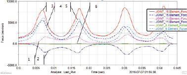
Fig. 2. Support reactions in the forces: 1 – on the Y axis, 2 – on the X axis of hinge 7 of the bottom trough; on the X and Y axes: 3, 4 – in the spherical hinge of the central link of chain 8; 5, 6 – on the Y and X axes in hinge 9 of the top trough (numbers of the design elements from Fig. 1, а)
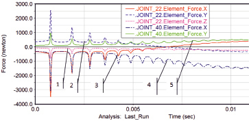
Now let us consider the scrapers movement for the group increased in the quantity up to the close simulation of the entire turn zone, Fig. 4, a. The quantity of the chain links between the scrapers varied and did not practically effect the characteristic elemental motions of the system. In different combinations in the group there was a scraper which stability was questionable. At the moment of the movement start the load in the support on the trough was the greatest, Figure 4b, and later on, with increasing the angle of hade it decreased and became minimum. This permits to make the assumption that the scraper instability is explained by sharp acceleration at the moment of the movement start, therefore it is necessary to analyze the loads combinations acting on the scraper and slowing down its movement and causing accumulation of energy for its transferring to acceleration. In Fig. 4, b it is curve 3 that has the maximum peak near the Y axis, though in the zone of the steady movement this load is already 4 times less than on curve 4 on hinge 40. When accounting the friction forces between the scraper and the conveyor bed the maximum effect on this process would be caused by the forces pressing the scraper to the bed. Therefore it is possible to assume that even with a static solution those scrapers will be most pressed to the bed. For the troughs which angle of hade made near 45 ° for X and Y projections the support reactions were close to those in Fig. 2.
The scraper instability was most shown at increasing the force acting on the chain in the opposite direction between which the angle was considerable and ideally reached 90 °. As usual at the initial moment of the movement the support reactions are pulsing and later on, after 0.05 sec., they are close to uniform (Fig. 4, b). Developing the entire rotary system does not lead to high-quality changes in loads. Modeling the complete turn zone shows that projections of the supporting forces change from the maximum to the minimum and vice versa on each scraper. On the length of the turn zone the projections to the X axis change from the minimum in the zone of the conveyor unloading to the maximum in the zone of binding the linear part of the conveyor. The analysis of the spectral density of the chain vibration shows that density of vibration of high and low frequencies on the rotary part with increasing the speed change but little with changes on the face part.
Conclusions
The studies carried out show that introducing a device with the transportation turning to 90 ° in the scraper conveyor mechanism makes basic changes to the dynamics of fluctuation processes and designing the scraper conveyor. The support reactions of the scrapers, speeds and accelerations arising in the turn zone, periodic changes of their values are generally defined by the transportation angle of rotation. There are developed methodological recommendations for modeling such devices taking into account geometry of real devices and their power parameters (dimensions, inertial characteristics, section, types of hinge joints and friction in them) [8]. The obtained results qualitatively coincide with the data of experimental observations and are quantitatively defined by random factors within designing and operation.
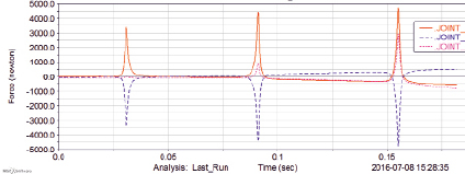
Fig. 3. Scraper instability with the spatial hinge in the trough support, maximum loads on Z: 1 – second; 2 – third
a
b
Fig. 4. Instability of one scraper in the group, rotation hinges 40 and 22 (hinges numbers in the model)
In the developed models of movement the vibration are caused by the absence of the friction forces of resistance to the scraper rotation relative to the central axis to which the chain is fixed. In reality the scraper rotation is interfered by the friction forces in hinges, scrapers on the elements of the troughs and due to their “dipping” in the transported weight. The friction force in the scraper support on the trough, on the contrary causes its inclination owing to the moment of the tractive force, but it can be interfered by the pair of forces developing the moment directed to the opposite side, arising due to the chain fixing to the scraper is really performed at two points, and when turning their inter-axial distance defines the shoulder of the pair of forces returning the scraper into the starting position. In the entire range the resultants of forces are generally identical, all the scrapers are pressed to the internal boards. The average load of the scraper support in the turn zone is defined by the number of scrapers. The obtained set of models and design expressions can consider all the stages of the scraper movement in the flexible system of the connected troughs that permits to establish dynamic differences of rotary scraper conveyors from conveyors for rectilinear transportation. So the number of scrapers on the length of the conveyor shall be increased not less than twice or thrice, scrapers shall be made stronger and have expanded supporting zones at the trough board. Supplying the system of the scrapers sliding and the troughs with the guides preventing large displacements of the scrapers in 3 planes would also be a universal solution. At the same time the constructive forces shall be directed to prevention of these zones of interface filling with rocks and free pass of the scrapers in the zones of the trough joints disclosure on the side that is remote from the center of the turn.
Библиографическая ссылка
Zhetessova G.S., Beisembayev K.M., Mendikenov K.K., Malybayev N.S., Madikhanova A.B. FEATURES OF DESIGNING CONVEYOR SCRAPERS AND CHAIN TURN ZONE DURING VIBRATION // European Journal of Natural History. 2017. № 5. ;URL: https://world-science.ru/en/article/view?id=33807 (дата обращения: 23.07.2026).