
Scientific journal
European Journal of Natural History
ISSN 2073-4972
ИФ РИНЦ = 0.204
KINETICS OF FATIGUE CRACKING OF THE MAIN STRUCTURAL ELEMENTS AND WELDED JOINTS BASIC BLOCKS OF FIXED OFFSHORE PLATFORMS

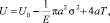
Continuous operation of steel offshore oil and gas constructions requires an assessment that leads to the necessity of introduction of fatigue criteria. Fatigue cracks can be such as a criterion. According to some experimental studies of different authors, strength of samples that model large-sized facilities sharply fell with the appearance of the fatigue crack with depth of 2–3 mm the sample stability, modeling large-sized facilities dropped sharply and they were destroyed with the voltage, that is less than the rate one [1, 2, 12]. In all the studies cracks caused fracture with law nominal voltage after their depth were more than 2–3 mm. These dangerous defects that can be formed in the main structural elements either in in welded joints represent quite a serious danger and may lead to the destruction of the construction in particular conditions [1–12]. Moreover, fatigue cracks can break vacuum rating of the offshore platforms, entail the leakiness with the further submersion. Cracks elimination is connected with unscheduled downtime that influences economic profitability of constructions. The importance of taking into account the requirements providing fatigue durability is recognized by all the leading worldwide organizations in the offshore development field. Firstly, concepts ‘fatigue” and “fatigue crack” are needed to be determined. Metal fatigue is a process of gradual damage accumulation in material effected by alternating voltage that caused by various loads and impacts [2, 3, 7–12] (temperature, corrosion and vibration) leading to metal property change and appearance of cracks. A crack, gradually developing and weakening a cross-section, causes sudden destructions of constructed elements and welded joints. Though during test model samples of the support block, cracks occurred in welded joints mostly, however, there was a case when the crack occurred in the main metal during experiments and caused test pattern fracture before crack occurred in welded joints. Also it needs to be stated that there were incipient cracks in the place where the test pattern was attached to the priming. The authors explain this fact by large value of bending moments occurring in the test pattern cross-section, attached according to a console scheme. It is well known that the basis mechanism causing fatigue crack development is effect of variable loads and impacts that, in turn, lead to changing with some frequency alternating voltage. Earlier, the authors systematized the concepts of load and impacts and described their influence on appearance and development of fatigue cracks. Mathematics methods are offered to describe those impacts and to determine their effects on the voltage condition of tested elements. In this article a solution to the important practical question is suggested, i.e. a process description of initiation, development and crack opening displacement for the main structural constructed elements and welded joints of the constructed block of the fixed offshore platform. The purpose of this article is to analyze the existing methods describing the kinetics crack growth and on the basis of it to devise a method describing those processes in welded joints and main constructed elements … Let us give a short description of basic concepts relate to cracking process. The key idea is so called elastic strain, that implies the energy of external forces, is expended on the element’s elastic deformation. All the work that is done during elastic deformation is saved as the energy, that restores the element after relieving [2, 12].
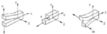
a) b) c)
Fig. 1. Tipes of cracks depending on the type of the applied load
However, if there is a crack in the element, the rate of the elastic force is changed. If the elastic deformation energy of the plate with no cracks at the given voltage level equals  then if there is a crack, it will be defined according to expression:
 (1)
(1)
where E – is the material’s modulus of elastic. The expression  shows the reduction of the elastic deformation energy of the plate because of the cracks, 2a – full length of the crack. The expression is built up from the assumption that if there is a crack in the plate, with the size 2a, there is no elastic deformation force in the material volume, that equals πa2. The value 4aT- crack’s surface energy, taking inti account the initiation of 2 surfaces; T – crack’s specific energy, that equals to the work that is necessary to form a new unit of surface. At first, the body’s full energy increases with the crack’s length increasing, which says that the crack’s growth can be only if there is voltage increasing. In this case there is a stable crack growth. If the crack growth reaches the critical dimension, cracks increase because of the elastic energy supply without any further increase in voltage. Such a crack development is called unstable. It is typical for brittle failures. Crack growth processes are described with the stress intensity factor K, that defines changes in the stress-strain state at the crack top. K values, taking into consideration a type of the applied load, by which the crack unstable deformations starts in plane deformation conditions, are called critical values of stress intensity factor KIc, KIIc, KIIIc. Depending on the types of the applied load, the body deformation with the crack can occur according to the following main schemes [12]; I – (tension, fig. 1, a) – the crack surfaces are diverging from each other; II (transverse cross, fig. 1, b) – the сracks are slipping one on the other in the transverse direction: III (the longitudinal dislocation, fig. 1, c) – the crack surfaces are slipping one on the other in the longitudinal direction.
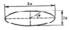
Fig. 2. The scheme of the elliptical-shaped crack
The stress intensity factor value K depends heavily on a crack type. In the author’s opinion, most of the cracks, both in welded joins and in the main structural supports, can be described with the elliptical-shaped crack (fig. 2). It can be explained by the experience observation of the crack growth, as cracks mostly initiate in the corners or on the edges of the body, where there is the stress concentration. Such cracks propagate into the body and have an elliptical or a quarter of an ellipse shapes. The stress state in such cracks, with the account of the crack surface curvature, is defined by Snedden and other authors [2].
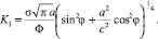
For the elliptical crack, the stress intensity factor is defined according to the formula.
 (2)
(2)
And Ф can be defined to an accuracy of 5 % according to the following formula:
 (3)
(3)
Table 1
Resilience steel weld at different combinations of welded steel
|
Welded steel |
Resilience + 20 °C kg – force/cm2 |
Resilience – 40 °C kg – force/cm2 |
|
Carbon steel + low alloyed or (chromium + molybdenum) steel. |
5 |
2,5 |
|
Carbon steel + austenite steel. |
5 |
2,5 |
|
Low alloyed steel or (chromium + molybdenum) + austenite steel. |
5 |
2,5 |
Table 2
The coefficients of the equation (15)
|
A0 |
A1 |
A2 |
A3 |
A4 |
|
1,2114378 |
– 1,6577755 |
11,743555 |
– 16,672913 |
9,7708125 |
The stress intensity factor has the maximum by values Φ = 90 °. Then the formula can be given in the following form [2]:
 (4)
(4)
 (5)
(5)
Knowing the stress intensity factor values, the crack growth speed can be defined, that is some function from them and is described by the kinetics diagram of the fatigue crack growth, the scheme of which is shown in the picture. It is important to state, that it is an unstable growth, in other words, it can be described by the three lots with the different growth speeds [12]:
I – low 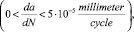
II – middle 
III – high 
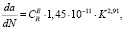
The critical Kfc and threshold Kth value factors are the border transfers from one lot to another one and the growth speed is calculated according to the formula:
 (6)
(6)
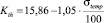
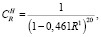
where a – a crack length increment at a cycle, (ΔK) – the stress intensity factor sweep, n and C – some material constants. The threshold stress intensity factor for steel constructions, including supported blocks of the fixed offshore blocks, can be calculated by G.V. Matokhin’s formula [4]:
 , (7)
, (7)
where Kth – is the threshold stress intensity factor, MPa•m0,5; σtemp – temporary steel resistance, MPa. In the basis that the temporary resistance, having been described in chapter 3 of the welded joint is 490 MPa, the value stress intensity factor will equal to 10,7 MPa•m0,5.
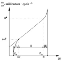
Fig. 3. Kinetic diagram fatigue fracture of welded joints and the major structural element of the fixed offshore platform
The empirically received formula in works [5] is offered to use by the authors to describe the kinetics crack growth:
 (8)
(8)
where a – the crack length increment at a cycle, ΔK – the stress intensity factor sweep,  is defined by the formula:
 (9)
(9)
where R1 – threshold factor of the asymmetry of the cycle, taken according to the work data [5]. After defining the parameters of the straight line II, describing the growth speed on the lop I and calculation of the threshold value stress intensity factor, it is necessary to dewher – fine the parameters of the straight line on lop II. For this purpose, the authors offers to use the equation, that is solved during the work [5]:
 (10)
(10)
where a – the length increment at a cycle, ΔK – stress intensity factor sweep,  is defined according to the formula:
 (11)
(11)
where R1 value is the same as the one in the formula (9).
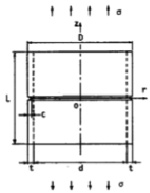
Fig. 4. Scheme of structural element of the offshore platform in the presence of a ring fracture
The proposed equation is valid until the critical stress intensity factor is reached KIc, that characterizes the unstable crack growth, that can be defined by the direct experimental methods according to GOST 25.506-85 or to use for the calculation of this value the dependency, proposed in this work [3]:
 (12)
(12)
where E – elastic modulus; v –poisson’s ratio, av – resilience on the Charpy type models; k – dimensionless ratio of the proportionality, calculated according to the formula:
 (13)
(13)
where σtemp and σm – temporary resistance and yield stress of steel. The study materials resilience can be defined from the data certificate, according to the normative documents; in some situations the data from RD RTM 26-298-78 (table 1) can be used.
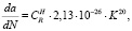
The result of the calculation shows that the threshold stress intension factor of the sudy welded joint is 29 MPa. The same principles of making a kinetic diagram are applied to the main constructed element of the supported block of the offshore stationary platform. On the basis of the available calculations, the authors created the kinetic diagram of fatigue destruction of the welded joints and the main constructed elements of the support blocks of offshore stationary platforms. For example, the value of the stress intensity factor for the brace support, representing a hollow tube if there is a surface ring crack both with the bending failure and tensile value of stress intensity factor, can be defined according to the following formula:
 (14)
(14)
where σ – intensity tensile and bending value, c – crack depth, counted from the surface, and F – the function, determined by the formula:
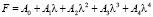 , (15)
where λ – relation of the crack depth C to the wall width of the t constructed element, and the corresponding rates are determined in table 2.
Библиографическая ссылка
Starokon I.V., Bazhenov A.G. KINETICS OF FATIGUE CRACKING OF THE MAIN STRUCTURAL ELEMENTS AND WELDED JOINTS BASIC BLOCKS OF FIXED OFFSHORE PLATFORMS // European Journal of Natural History. 2017. № 3. ;URL: https://world-science.ru/en/article/view?id=33742 (дата обращения: 02.08.2026).