The isodeparaffinization unit for diesel fuel considered in the work is designed to produce arctic diesel fuel and diesel fuel MK1 that meet the requirements of the environmental quality standard “Euro-5” with minimal output of product oil. The technological process of diesel fuel isodeparaffinization is one of the methods of dewaxing petroleum products currently used in the oil refining industry. The purpose of dewaxing petroleum products is to reduce the pour point of petroleum products and improve their low-temperature properties. The unit is a new designed production facility, belonging to complex and hazardous industrial objects. The main units of the isodeparaffinization technological process of diesel fuel are: reactor block, separation section, fractionation block, compressor block. This article is dedicated to the automation issues of the fractionation column (fractionation block).
The purpose of the product fractionation block is to remove hydrogen sulfide, light fractions, and unstabilized oil from the liquid with a low-pressure cold separator, and to separate the liquid reaction products into stabilized oil and arctic diesel fuel for options 1 and 3, or stabilized oil, arctic fuel, and diesel fuel MK1 for options 2 and 4.
The liquid bottom product from the reboiler column product enters the product fractionation column into the vaporization zone above plate 35. The vapor phase of the top product of the product fractionation column is completely condensed in the condenser of the top product column, and the liquid condensate is directed into the top product tank of the product fractionation column. Liquid hydrocarbons from the spray tanks are pumped by the top product pumps of the product fractionation column, with part of the liquid directed back into the product fractionation column as spray, and the remainder cooled in the end oil cooler and directed to the plant’s common storage. Water collected in the settling tank of the top product tank of the product fractionation column is pumped by acidic water pumps, mixed with acidic water from the spray tank of the reboiler column product, and directed to the off-site acidic water degasser of the hydrocracking unit 4100.
The top product of the fractionation column is completely condensed in the air cooler. The condensed liquid then enters the spray tank of the product fractionation column.
The liquid side stream is taken from plate 20 of the product fractionation column and fed into the MK1 diesel fuel product pumps.
The bottom product of the product fractionation column is a dewaxed product of arctic diesel fuel, which is pumped by the bottom product pumps of the product fractionation column. Part of it goes to the reboiler of the product fractionation column for heating and is directed back to the bottom of the column, while the rest is cooled by passing through a series of heat exchangers.
Materials and methods of research
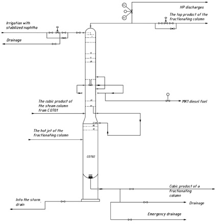
The effective operation of technological processes largely depends on the correct formulation of automation tasks. An important stage in the development of an automation system is the analysis of the main apparatuses as control objects, i.e., identifying the characteristics of disturbance and control channels (Figure 1) [1]. The analysis of the technological process as a control object carried out in this work will allow determining the structure of the control system, i.e., selecting control actions that are imposed on the object to change the controlled variables.
Analysis of the technological process as a control object. The control object is an object or section of a technological line, the management of which achieves the desired result. The control object in the fractionation block is the product fractionation column pos. C0702. The considered technological process is continuous.
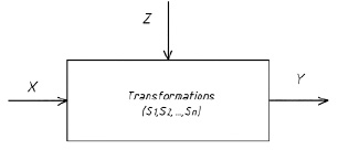
Solving analysis tasks involves a comprehensive description of the existing influences in the system (Figure 2) for subsequent derivation of transformations – regularities by which input influences are converted into reactions.

Fig. 1. Technological Control Object

Fig. 2. Description of Coordinate System: X – control input; Z – disturbance input; Y – controlled coordinates; S – transformations

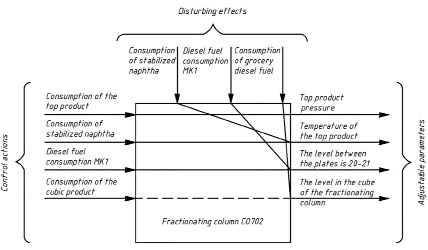
Fig. 3. Informational Diagram of the Control Object
Control input X is set by a human or generated by a control device. Control inputs are quantities whose values can be varied during the control process. Disturbances Z are independent of the control system. They can arise both outside the system – external disturbances, resulting from changes in input parameters, some output parameters, and environmental parameters, and inside the system – internal disturbances.
Defining the normal technological mode involves specifying a list of parameters whose values need to be maintained at a certain level, as well as indicating the ranges of values within which changes in these parameters do not lead to serious disruptions of the technological mode. Control of the technological process boils down to maintaining parameters at a level corresponding to the normal technological mode [2].
Figure 3 illustrates the structural diagram of influences affecting the process taking place in the fractionation column.
In real operating conditions, when various disturbances affect the control object, the dynamic mode of operation of the objects becomes the characteristic mode [3]. Analyzing the technological process as a control object allows for the selection of the control system structure, i.e., determining which control action should be used to manage a particular state parameter [4]. Cascade control systems are applied in the considered process to improve the quality of regulation of technological parameters, where disturbances are compensated for using regulators.
Cascade control schemes include two or more sequentially connected regulators, where the first regulator in the cascade affects the control valve, and subsequent regulators change the setpoint for the previous regulator. The setpoint remains unchanged for the last regulator in the cascade, making it the primary regulator of the cascade.
In the temperature control loop of the upper product of the fractionation column, the first regulator is the flow regulator of the stabilized naphtha used to compensate for disturbances related to changes in pressure drop in the stabilized naphtha supply line to the fractionation column. The second regulator is the temperature regulator, acting as an external regulator and generating a control input that changes the setpoint for the first regulator.
In the level control loop of diesel fuel MK1, the first regulator is the flow regulator of diesel fuel MK1 used to compensate for disturbances related to changes in pressure drop in the MK1 diesel fuel supply line to the fractionation column. The second regulator is the level regulator, acting as an external regulator and generating a control input that changes the setpoint for the first regulator.
In the level control loop of product diesel fuel, the first regulator is the flow regulator of the cubic product used to compensate for disturbances related to changes in pressure drop in the product diesel fuel line. The second regulator is the level regulator, acting as an external regulator and generating a control input that changes the setpoint for the first regulator.
The control input for regulating the pressure in the upper product line of the fractionation column is the flow of the upper product.
In addition to controlled technological parameters, there are monitored parameters: temperature of the cubic product of the flash column at the inlet; pressure drop in the upper, middle, and lower sections; pressure drop between trays 22-34; temperature of the cubic product of the flash column at the outlet; high pressure of the upper product at the outlet of column C0702; pressure in the fractionation column; pressure of the cubic product of the fractionation column; temperature of diesel fuel MK1.
Results of the research and discussions
Analyzing the technological process as a control object has shown that the process requires control and management of numerous parameters [5]. To automate production, a three-level automated process control system (APCS) is proposed. APCS will allow maintaining the optimal technological process without constant personnel presence to achieve maximum efficiency. APCS will solve a number of tasks:
1. Monitoring process parameters: automatic control of temperature, pressure, raw material and reagent flow rates, as well as product composition.
2. Regulation of parameters using high-precision sensors, valves, actuators, which optimize the process and ensure stable product output.
3. Diagnostics and prevention of emergencies. Automatic diagnostic systems quickly detect problems in the process and prevent accidents.
The automation system of the fractionation column should:
1. Control and manage the separation process of the cubic product entering the column into the necessary types of diesel fuel, including controlling parameters such as temperature, pressure, raw material and product flow rates, and column liquid level.
2. Monitor the condition of equipment, including controlling the operation of pumps, valves, sensors, and other system elements.
3. Ensure process safety by monitoring parameters and automatically shutting down the system in case of emergencies.
To perform the listed functions of the automated control system, the interaction of its following components is necessary: technical, software, information and organizational support, as well as operational personnel.
The technical support of the automated control system is a set of technical means, which includes computing and control devices; means of receiving (sensors), converting, storing, displaying and registering information; signal transmission devices and actuators [6, 7].
The set of programs necessary for the implementation of the functions of the automated control system, the specified functioning of the complex of technical means of the automated control system and the intended development of the system is the automated control system software.
The information support of the automated control system includes information characterizing the state of the automated technological complex; classification and coding systems for technological and technical and economic information; arrays of data and documents necessary to perform all functions of the automated control system, including regulatory and reference information.
The organizational support of the automated control system is a set of descriptions of functional, technical and organizational structures, instructions and regulations for the operational personnel of the automated control system, ensuring the specified functioning of the operational personnel as part of the ATC.
The operational personnel of the automated control system includes: technologists – operators who monitor the operation and management of the control system using information and recommendations on rational management developed by the complex of technical means of the automated control system; the operational personnel of the automated control system, ensuring the correct functioning of the complex of technical means of the automated control system.
The paper proposes to implement a three–level automated control system, at the lower level of which measuring devices and actuators are concentrated; at the middle level – a software logic controller with a programmed control algorithm and at the upper level – a computer-based operator station with pre-installed software.
Overall, the APCS should meet the requirements of accuracy and reliability of process parameter control, quick response to parameter changes and emergencies, ease of use for operators and technical staff, scalability, data protection and confidentiality, availability of backup power and emergency shutdown, compliance with safety and environmental standards. Moreover, the system should ensure high efficiency and reliability of the production process.
Conclusion
The presented work has developed a set of measures and proposed technical solutions for creating a control system for the fractionation column in the diesel fuel isodewaxing process, which has brought the safety level into compliance with regulatory requirements and improved the quality of automatic control of the existing technological object.
Библиографическая ссылка
Mumdzhian D.A., Kechkina N.I., Pavlycheva T.N., Kuligina N.O. DEVELOPMENT OF A CONTROL SYSTEM FOR A FRACTIONATION COLUMN IN THE ISODEPARAFFINIZATION PROCESS OF DIESEL FUEL // European Journal of Natural History. 2024. № 2. С. 8-12;URL: https://world-science.ru/ru/article/view?id=34381 (дата обращения: 07.02.2026).
DOI: https://doi.org/10.17513/ejnh.34381

