
Scientific journal
European Journal of Natural History
ISSN 2073-4972
ИФ РИНЦ = 0.204
APPROACHES TO THE CREATION OF ENERGY EFFICIENT ELECTROMECHANICAL DEVICES FOR SELECTIVE DISPERSION MATERIAL

Electromagnetic mechanical activators with magnetic liquefied layer can be implemented in various constructive forms [1, 2, 3]. EMMA design covers a range of problems, the solution of which should be to strive for the optimal ratio of parameters such as the effectiveness of the product dispersion process, economical design of the device, selective dispersion and energy efficiency of production lines processing industries.
In the development of EMMA put the problem of optimal use of materials, reduced energy costs, simplify design and improve reliability. EMMA model features due to the technological requirements for carrying out the process of grinding the product, taking into account the change in its physic-chemical and organoleptic properties in the mechanical, physical and thermal treatments [4, 5, 6] .. Of great importance in the design, challenges become associated with study the adjustment capacity and performance management. The ability to fine and safe management of physical and mechanical processes in magnetic liquefied ferromagnetic elements layer allows you to create devices with high selectivity materials grinding process [7, 8, 9].
The aim of the study is to develop a methodological approach to solving design problems of electromagnetic mechanical activators EMMA providing selective grinding materials.
Material and research methods
Object of research are methods of designing EMMA design parameters based on the analysis of the magnetic state of the system.
Results of research and their discussion
Fig. 1 shows the structural form of an electromechanical device that implements the method of forming the electromagnetic force in dispersing magnetic liquefied layer ferromagnetic elements. The design concept and principle of action of the device are the subject of the invention (RF patent № 1457881). EMMA comprises actuator, the container 1 for placing the product treated with the loading and unloading two nozzles 3, the grinding elements 4, permanent electromagnets 5 and 6 with adjustable current windings 7 and 8 controls. The magnet 5 is placed in the container 1, fastened with the possibility of rotary motion to the shaft 9 and has barbs on the outer surface 10. The magnet 6 is fixedly fastened outside the container 1. Inside the container 1 installed partition 11, which are placed between the grinding elements 4 are made as cylindrical ferromagnetic cores designed for forming the outer surface of the magnet 5. The height of the teeth 10 smaller in diameter than the rods 4. to supply the coil 7 are installed on the shaft 9 of the brush contacts 12.
The device operates as follows: in the working volume of the reservoir 1 is pumped through the pipe 2 to be processed product. Drives the shaft 9, which is mounted on the magnet 5 with the teeth 10. At the same time through the sliding contact 12, power is supplied to the coil control 7. Power is also supplied to the coil 8. The electromagnetic forces cause arisen grinding elements 4 are attracted to the surfaces of the magnets. From the grinding elements 4 are formed various spatial constructions in the intervals between which receives the processed product.
The magnitude of induction in the gap between the magnets 5 and 6 depends on the current in the control windings 7 and 8 and determines the degree of exposure of the grinding elements on the treated product. Available on the magnet surface 5 tines 10 provide a secure grip elements 4 with the surface. The drive motor as applied three-phase motor with wound rotor (P = 3 kW, n = 1470 rev / min). The regulation of high-speed modes of operation carried out by a speed variator, controlled strobotuners ST-5 having the basthic error of not more than – 0,5 % of reading. Power control windings is made from the switchboard via the contacts for automatic switch and bridge rectifiers, diodes built D-245A. magnetic induction of constant magnetic field produced using the milliteslametr portable universal (TPU). To measure the speed used by a digital tachometer AKIP-9201.
After filling the working volume processed product and the grinding elements include a drive motor, set the inner cylinder speed EMMA and the current in the control windings. When power is applied to the winding current arise electromagnetic force under the influence of which the ferromagnetic grinding elements form the spatial construct, carrying a mechanical connection in the form of strikes and friction each other and surfaces of the product layer by electromagnets. The product passes through the working volume of the container is exposed to various deformations: compression, abrasion, impact and shear. Grain size distribution and the degree of comminution of the material was determined the device “FRITSCH-4M”.
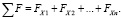
Assuming concentrated winding control device on the stationary part and on the basis of the above, for each x-th section of the magnetic circuit KPX dispersion ratio is determined from the following expression:
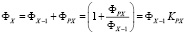 , (1)
, (1)
where ФX–1 – the magnetic flux in the x-1 site;
ФPX – magnetic leakage flux;
KPX – magnetic flux leakage coefficient as it moves from site x to site 1-x (KPX > 1).
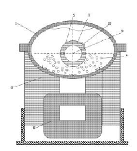
Fig. 1. Electromechanical device EMMA (RF patent № 1457881): 1 – capacity; 2.3 – feed and discharge pipes; 4 – grinding elements; 5.6 – electromagnets; 7.8 – adjustable current winding; 9 – shaft; 10 – teeth
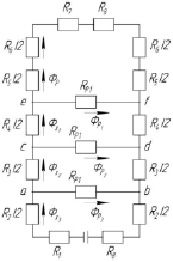
Fig. 2. The equivalent circuit of substitution magnetic circuit EMMA
The magnitude of the magnetic flux ФPX is determined by the difference of magnetic potential and magnetic resistances between points on the magnetic path of the respective streams scattering. In engineering calculations (in order to simplify their permissible) presence of stray magnetic fluxes into account by using a correction factor of KP, which is calculated as a ratio of ФOY magnetic flux produced by the magnetizing force control winding to the magnetic flux in the working volume ФP.

KP size ranges from 1.1 to 1.3.
Methods of calculating the magnetizing force FX x-th area of electromechanical devices:
1. It determines the value of ФX, taking into account the scattering of magnetic flux.
2.  is calculated by the formula BX on the magnitude of induction stations (here – the SX this magnetic sectional area portion).
3. For the induction of values BX to B = Φ(H) graphical dependencies defined numerical value of HX. Tension in the individual sections of the magnetic circuit may also be calculated by the formula:
 ,
,
here, μX – magnetic permeability of the section.
4. Taking in to account the values of the average length of the magnetic field lines are calculated values 
 separate sections.
In the calculation of the magnetic circuit must be considered that the cross-sectional area portions with a radial direction of the magnetic field lines substantially changes along their length. Calculation magnetomotive force required for the magnetic flux in these areas is performed as follows.
If the value for induction station BX max varies sectional diameter D1 to BX min in section on a diameter of D, then x unsaturated portion BX max and is located on the characteristics of the linear part B = Φ(H). The calculation is carried out according to the formulas:
 ,
,  ,
,
 ,
,
here lX – sectional area x length in the axial direction; HXCP – the average value of the magnetic field strength, HX max and HX min – the maximum and minimum value of the tension at the site of the values of BX max and BX min.
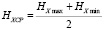
If the dependence of BX and HX on the current plot is linear, it is necessary to determine the value of HXi for the greatest possible number of sections spaced at equal distances from each other. The average value of tension is determined by the formula:
 , (2)
, (2)
where т – number of sections.
Thus, by setting the shape and constructive geometric dimensions EMMA properties and filler materials for manufacturing the magnetic core portions can determine the total or resultant magnetomotive force (M.M.F.) to be established by the current flowing through the winding (or windings) Control to allow passage of magnetic flux calculation value. To do this, we calculate a value of the magnetic field strength on selected portions HX of the magnetic circuit EMMA:
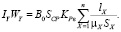 (3)
(3)
For structural shapes EMMA shown in Figure 1, the following expression for the calculation of the resulting M.M.F.:
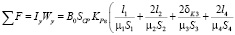
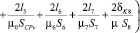 , (4)
, (4)
where l1, l2, l4, l5, l6, l7 – length sections I, II, IV, V, VI, VII;
δK3, δK8 – structural gaps;
μ1, μ 2, μ 4, μ 6, μ 7 – permeability magnetic material portions at certain values of induction;
μ0 – permeability working volume filled with a working ferromagnetic bodies and milled product, for given values of the induction;
μv – magnetic permeability of air;
 – cross-sectional area of the magnetic areas;
SCP = L1L – area through which magnetic flux passes current in the working volume;
L – working volume length in the axial direction;
L1 – length of the working volume along part of its circumference within the area of the magnetic field EMMA.
On the basis of the calculation of the total M.M.F. (And calculating the winding or control winding) specified dimensions of the window (or windows) to accommodate the control winding. The magnetic sketch amended subsequently clarified total M.D.S. winding (or windings) control.
Methodology to evaluate the magnetic state of the magnetic EMMA:
Assuming the next induction values in the working volume  (KP = 0,2…1,25), in each case calculated value M.M.F. Control windings necessary for the magnetic flux of the magnetic circuit portions ФP. According to the calculations it is plotted
  characterizing the state of the magnetic device. This relationship defines the characteristics of EMMA to the extent that the current management. Using the values dependencies Pτ = Φ(B0), Pτ values determined for a number of values defined by the induction in the working volume [9, 10, 11]. EMMA, which has a magnetic operating point (nominal value in the working volume induction) on the linear part of characteristic
  is magnetically unsaturated. At the same time the degree of saturation of the magnetic steel has a significant influence on the properties of the device. The saturation state violated the conditions of formation of regulated power contacts in the system “particle layer magnitoozhizhennogo – particles of processed product”. Those. violated conditions for effective selective crushing of materials.
Conclusion
Presented in the article are techniques applied in nature and contain practical recommendations for improving the characteristics of EMMA, the introduction of which in the production lines can improve the energy efficiency of domestic industry production by producing products with a given technology, particle size distribution (given selective grinding) [11, 12, 13].
Библиографическая ссылка
Bezzubtseva M.M., Volkov V.S. APPROACHES TO THE CREATION OF ENERGY EFFICIENT ELECTROMECHANICAL DEVICES FOR SELECTIVE DISPERSION MATERIAL // European Journal of Natural History. 2017. № 3. ;URL: https://world-science.ru/en/article/view?id=33741 (дата обращения: 01.07.2026).