
Scientific journal
European Journal of Natural History
ISSN 2073-4972
ИФ РИНЦ = 0.204
ELECTRONIC TRANSFORMER WITH THE FREQUENCY REGULATION

There are known, for example, electronic welders of inventor type with the one-cycle or two-cycle (bridge) transistor inverter, which is loaded to the welding radio-frequency (till 100 кГц) transformer: «Transpocket 1400» - production of Austria, «Castolin GmbH» - Germany: «DC200A1» - Technothrone, Russia: «Inverter U 130-S» - Linkoln, USA and others.
Welding transformer in the mentioned devices is connected through the one-cycle or two-cycle rectifier to the smoothing throttle and load (electric arc), with the shunted inverse diode. The control system has closed system of regulation with the pulse-width modulator (PWM).
While this the use of expensive transistor modules with the opto-isolator and individual sources of displacement of each module makes more difficult and expensive the installation. To the shortages we should attribute the limited functional possibilities, because the regulation of frequency of exit voltage is suitable in the short range and basically in the inventors of resonant type, that is with the in-series the load condenser, and also higher losses because of saturation in the chain of supplementary transformer.
In the [1] there offered the new universal principle of direction of force transistors, which allows to decrease losses and to widen the functional facilities of device.
The work of device is carried out by following way.
While the plugging of the installation the self-excited oscillator 7 transforms the direct-current voltage at the input to the voltage of rectangular shape of high (till 100 kHz) frequency. ЭThis voltage transforms into the secondary winding 11, 12, 13 and thereby comes to the synchronizing entry of modulator 26, which corresponds the type microcircuit. Subject to signal of task U3 and factual signal of feedback Uф (fig.1) exit signal of modulator transforms the symmetric "meander" of voltage of winding 13 to the sign-changing impulses, "wideness" of which decreases while the increase of signal of task U3.
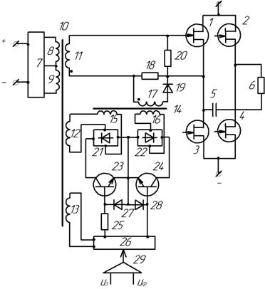
Figure 1. Scheme of transistor transformer
At the limit minimal "width" t ≥ tв, where tв - time of blocking of the transistor of inventor.
Accordingly, modulating transistors 23 and 24 are turned out being open at the different intervals of time. These transistors shunt by turn the diode bridges 21 and 22.
The switching of transistor 23 leads to the voltage to the winding 15 of supplementary transformer, and its switching-off with the simultaneous switching of the transistor 24 leads to the blaking of transformer 14 and to the zero voltage at its all windings.
The voltage of winding 17 of supplementary transformer 14 is algebraically sum up with the voltage of operating secondary winding 11 of basic transformer 10, as the result at the operating inputs of inventor´s transistors arises the voltage of unblanking and blanking. Since the windings 11 and 17 in the diagonal pair of transistors 1, 4 are connected with the ends, transistor pairs come unlocked antiphased, at the diagonal of inventor arises the voltage, the acting meaning of which is defined with the signal of task U3 at the input of automatic regulator, and the frequency is invariable and is set with the autogenerator 7, which can be carried out by any known scheme of autogenerator.
The condenser 5, which is turned on sequentially with the load 6, secures the absence of constant part in the voltage, what is very important if the load is the transformer (for example welding). The condenser 5 also secures the doubling of amplitude of voltage at the load, what is very important for welding transformers, because it improves the conditions of ignition of an arc.
It should be noted that the load can be any different but it can be transformer. In this case the condenser 5 can be excluded from the device. Indeed, introduced principle of direction of force transistor is universal and can be used for very different transistor transformers with the latitudinal impulse regulation.
Supplementary transformer unsaturable works in the conditions "switched on -switched off", what dramatically decreases losses and accordingly allows to decrease the power of self-excited oscillator.
References
1. Patent of RF N 2165125. Transistor transformer / Magazinnik G.G., Magazinnik L.T. - 2001. - Published in the bull. N 10.
The work was submitted to international scientific conference «Modern High Technolgies», Egypt, February 21-28, 2010, came to the editorial office оn 07.03.2010.
Библиографическая ссылка
Magazinnik L.T. ELECTRONIC TRANSFORMER WITH THE FREQUENCY REGULATION // European Journal of Natural History. 2010. № 4. ;URL: https://world-science.ru/en/article/view?id=21059 (дата обращения: 17.05.2026).