

Features of the production of polymer films
The variety of types of films used determines the variety of methods of their production. The main volume of polymer films produced in the world falls on films from molten plastic masses, which are based on polymers that are capable of passing into a viscous or highly elastic state when heated, without undergoing thermal destruction.
The method of film production is determined by the chemical nature of the polymer and the purpose of the finished product. Currently, it is possible to identify four groups of methods for making a film from a polymer in a viscous or highly elastic state: extrusion, calendering, production of combined films, physical and chemical modification of films.
Today, the most common method of obtaining a sleek polymer is extrusion. Extrusion is the technological process of molding products by continuous or periodic pressing of the material in a plastic or viscous state through the forming tool-head. The profile of the head orifice determines the configuration of the product.
In the plastics industry, the extrusion method is widely used for the production of pipes, profile products, sheets, films and fibers, for coating rolled materials (paper, fabric, metal foil, polymer films), food and industrial packaging, wire and cables, as well as for the production of blown products [1].
This method has received a wide spread in practice due to the simplicity of implementation and the ability to process the most common polymers such as polyethylene, polypropylene, polyvinyl chloride into films and etc.
Analysis of trends in the development of bag film lines shows that due to using special control methods, the operation of extrusion plants becomes even more efficient and economical. When developing a new generation of technical tools that control equipment, manufacturers take into account current trends and developments in the field of industrial automation. At the same time, there are high requirements for automation and control of bag film lines, since the possibilities of the extrusion-inflatable method are not fully used. First of all, this applies to maintaining the same thickness of the film in all its sections. The task is to create a system of automatic control of the process of obtaining an equidistant polyethylene film using the cooling system of the film blank.
Given the complex relationship between the parameters of the extrusion-inflatable method, it is necessary to use mathematical modeling methods. Bearing in mind the most important task of improving the quality of plastic film, it is necessary to consider the main ways to solve it.
As a result, the main tasks are:
1) to conduct theoretical and experimental studies of the process of obtaining a polyethylene film by extrusion-inflatable method, including to establish the relationship of the parameters of the cooling system of the film blank with the main indicators of film quality;
2) build a mathematical model of the influence of the cooling system on local changes in the thickness of the polyethylene film;
3) based on the obtained models to develop an algorithm for automatic maintenance of film thickness;
4) develop and implement a device that allows you to automatically adjust the thickness of the plastic film based on microprocessor technology [2].
Calibration of film thickness
One of the most important indicators of the quality of a plastic film is the calibration of its thickness. As the calculation of the mechanical strength of film products corresponds to mechanical strength of the thinnest section, it is obvious that an increase in the film thickness leads to an unjustified overspending of polyethylene (1 % of the thickness difference corresponds to 1 % overspending), an increase of the total cost of the product, and sometimes to a deterioration in its operational characteristics.
To obtain the same film thickness, along the entire perimeter of the film sleeve, the melt must exit the forming head gap with the same volume velocity and constant viscosity, in any unit volume; under such conditions, inflation of a cylindrical billet with constant air pressure inside the sleeve at equal peripheral cooling (without any local cooling or hot air flows) can result in a more or less equal-thickness film.
The conditions for obtaining an equal thickness film are:
1) ensuring the same volumetric extrusion speed in all sections of the annular gap. This condition is easily fulfilled on direct-flow heads (for pipes). The angular heads, used in the production of film, have a significant design flaw; unequal length of the paths traveled by the melt particles from the end of the screw to different sections of the forming gap. Constructors try to smooth out these differences in practice by turning the flow in a wide section of the channel and creating a significant pressure drop in the vertical part of the annular channel. However, even in these cases, the excess melt flow in the portions of the gap adjacent to the cylinder has to be suppressed by artificially narrowing of the forming gap in this part with the gap calibration. To inhibit the flow, in addition to the general adjustment of the gap value with the help of centering bolts, braking of various parts of the flow using deformable forming rings are used. Usually, the expansion or narrowing of the gap with the help of exhaust and pressure bolts is carried out according to the results of a circular measurement of the film thickness, drawn on special pie charts.
2) the constancy of the temperature (viscosity) of the melt. To maintain a constant melt viscosity, homogeneous polyethylene must be used in terms of molecular weight, melt index, and particle size distribution. The smaller the deviation on these indicators, the greater the probability of obtaining an equal-thickness film. Due to the rheological properties of the polymer, the melt temperature has a qualitative effect on the viscosity of polyethylene and its speed. An increase of temperature leads to a greater thinning of the film due to a drop in viscosity and an increase of the cooling and stretching time of the film before crystallization. Practically, the inflation of the sleeve ceases at the moment of crystallization of the polyethylene melt at 100-110 ° С, which is manifested in a noticeable turbidity and whitening of the transparent sleeve. The wavy configuration of the crystallization line indicates the presence of hotter and cooler sections of the sleeve (at an uneven temperature of the outgoing mass in different areas around the perimeter of the sleeve). The design of the head should ensure evenness heating of the flow and the constancy of heat loss by the melt flow around the entire perimeter of the section.
3) the end point in the process of forming the sleeve is the cooling system. The constancy and uniformity of cooling of the hot workpiece should be ensured by the design of the blowing ring.
Under ideal conditions of melt preparation and molding, a defect in the cooling system can lead to the occurrence of different thicknesses [3].
From the above it can be seen that the calibration of the film thickness is associated with great difficulties. A change in one parameter of the technological process entails a change in a number of factors affecting the processes of flow, inflation and cooling of the film.
For example, during calibration, when the gap is reduced in any part of the gap, the:
1) polyethylene melt yield reduction;
2) a relative increasing of the yield due to an increase in the shear rate and a decrease in the effective viscosity;
3) increase in yield due to some increase in temperature as a result of increasing shear rate;
4) changing the productivity due to changes in the melt temperature due to changes in the duration of the mass flow in this section of the head;
5) increasing of the film inflation by reducing its thickness and viscosity of the melt coming out of the head;
6) attenuation of inflation due to faster cooling in the shaft of the thin section;
7) fusion on a given section of the film during the flow and inflation of adjacent sections of the film or melt;
Therefore, even the best designs of modern film heads do not yet provide an equidistant thickness of the film obtained by blowing less than 5 %, and such equipment requires large investments.
However, the above problems of equipment based on this method is constantly in the process of solving, implementation of improvements and flows into modifications of individual components and mechanisms of the equipment.
To ensure the stable operation of the plant, improve the efficiency of technological process (TP), as well as increase it`s level of safety, it was proposed to introduce an automation system based on computer technology that provides high reliability and speed of information processing, and also to organize an operator station that will perform the functions of visualization, storage and processing of information [4].
Hardware
As a cooling air ring, we use a ring with four air passes and using the aerodynamic effect of the jet. The ring is divided into sectors by internal partitions corresponding to each entry of air. To provide cold air into air ring we use radial fans BP 300-45 type: supply voltage – 380V, IP54, 3000 rpm, 3000 m3/h. To change the fan performance, Hitachi l 100 – 007 NFE frequency converters are used to control the rotation frequency of asynchronous fan motors: output frequency: 0.5-360 Hz, control from the controller by a universal analog signal of 4-20mA.
The PLC is taken from the EN-150 TYPE IV microcontroller family of Hitachi Industrial Equipment Systems Co., Ltd, it includes:
– Power supply module: EH PSA, rated voltage 85-264V, output voltage 5V 3.8 A, 24V 0.4 A;
– Processor module: CPU 448, 1024 I/O channels, RS485, RS232;
– Eh-AX8I analog input module: 8 channels (4 ... 20 mA), 24V power supply;
– Eh-AY4I analog output module: 4 channels (4...20 mA), 24V power supply;
– Eh-XD16 digital input module: 16 channels, input voltage 24V;
The cooling system control unit includes:
– The thermoelectric Converter STNK 02.09.: the range of operating temperatures from 0 to 200 °C
– BOOST 2: thyristor and triac control unit is designed to convert 4-20mA input signals into control signals for the thyristors or triac located in the heating element control circuits.
– TS triac-122-25-12: to control the amplitude of the voltage applied to the heater;
– heater: nichrome 1000 W;
– ultrasonic thickness gauge Magna-Mike 8600: scan: min:0-4mm, max: 0-400 mm, thickness indication Accuracy: 0.001 mm;
– absolute pressure sensors Eni-12R-DA 2051: supply voltage 12...24V, output signal 4...20mA, IP66;
– thermal converter OVEN 50M: power supply 24V, output signal 4 ... 20mA, measuring range -50...+180 °C
If it`s necessary, using the RS-485 data transfer interface, you can check the status of the control system from any remote computer at any time.
During operation the system is in the following States:
– data entry mode;
– manual operating mode;
– automatic operation.
In the input mode, you can enter data about the film that you want to get in the end, collect information from the working sensors.
In manual operation, the operator has the ability to manually control the performance of all cooling fans and temperature
In automatic mode, the system automatically analyzes the data received from the sensors, selects the coefficients to create the necessary air flow for each sector. The operator can observe all changes on the operator panel.
Software
As the software for operator stations, we choose Windows 10PRO.
To program the controller, the CoDeSys (Controller Development System) industrial automation tool software is used, as it is declared by the controller manufacturer as necessary.
Operation algorithms:
The control algorithm is divided into three stages:
– input of parameters of the received film and initial survey of sensors of cooling system;
– coarse control of the film thickness using changing the flow rate of the cooling air;
– precise control of the film thickness using changes in the cooling air temperature.
At the first stage, the estimated film thickness is entered and the system is initially surveyed to obtain data on the flow rate and temperature of the cooling air.
At the second stage, test measurements of the film are made at the maximum air consumption and when the fan is turned off. Based on the results of the first response to changes in air flow, the expected change in the film thickness is constructed using n = 3 points (the point of initial measurement, the point with the maximum air flow, the point with the fan turned off, taking into account the proposed mathematical model). By entering the proposed change in flow rate, the actual thickness of the film is determined. Taking into account the obtained measurements, the estimated changes in the film thickness by n = n + 1 points, etc. are constructed. If the film reaches the set thickness range, the air flow is stabilized.
At the third stage, the necessary cooling air temperature is selected to achieve the best equidistance using the half-division method.
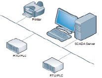
Structure of the Standalone concept
At the moment, there is a large number of possible configurations of the system for the implementation of work on a separate technological process, and on a huge, significantly geographically distributed production. In the presented project, it would be enough to use the simplest configuration, called Standalone, where the runtime and development environment is on one machine (full-featured SCADA) [5].
The structure of the Standalone concept is shown in figure.
In the end, we made an economic calculation of the cost of implementing the automation system in the process of gasoline shipment. It showed that the use of such a system is beneficial for implementation.